
How a Pipe Heating System Prevents Solid Buildup in Etch Lines
In a wet-etch operation, a blockage rarely begins as a dramatic event. It often starts as a slightly cooler section of line, a slow drift in pressure drop, or residue found during a maintenance check. A correctly engineered pipe heating system helps reduce that risk by keeping the process fluid within its validated temperature window from the source to the point of use. That is different from simply making a chemical hotter: the goal is to avoid uncontrolled thermal gradients that can change viscosity, phase behavior, or solubility along the route.
From a semiconductor equipment-integration perspective, the question is not whether heat is available. The practical question is whether every wetted section that matters sees stable, measurable conditions. Wet processes use acids, bases, solvents, and water, so temperature control, compatible materials, and a clean delivery path must be considered together. The discussion below is a technical framework, not a chemistry-specific setpoint recommendation; qualified process and EHS teams should validate conditions for the actual formulation.
Why solids appear in etch delivery lines
Solid buildup can arise when a formulation encounters conditions outside the envelope in which it was prepared, stored, or qualified. A local cold spot may change the balance between dissolved and undissolved material. Evaporation, contamination, incompatible materials, stagnant legs, dilution errors, or a reaction upstream can also contribute. The visible deposit is therefore an observation, not a diagnosis.
Temperature deserves attention because a line is not thermally uniform by default. Long runs lose heat to their surroundings; valves, fittings, supports, and uninsulated instrument sections can behave differently from straight pipe; and intermittent flow gives the fluid more time to equilibrate with the environment. In a process that depends on elevated, controlled liquid temperature, the heater is part of the high-purity fluid path rather than a separate utility concern.
What a pipe heating system actually controls
A pipe heating system typically combines a heat source, sensors, control logic, insulation, power distribution, and installation practices that keep the line within a defined operating band. Depending on the application, the heat source may be electrical trace heating, a fluid-based circuit, or another compatible method. Its value is not a single temperature number; it is the ability to limit temperature variation over the actual geometry and duty cycle.
A useful design review separates three temperatures: the source temperature, the outer-pipe or jacket temperature, and the process-fluid temperature at meaningful locations. These are not automatically the same. Sensor placement, thermal resistance through the wall, flow rate, ambient exposure, and the response of the control loop all affect the difference. Before accepting a design, confirm which temperature is being controlled and which temperature is being verified.
How a heating jacket reduces cold spots
A heating jacket adds distributed heat around a vessel or pipe section, which can be useful where localized losses would otherwise pull the fluid below its validated condition. For piping, a pipe heating jacket must fit the geometry, accommodate fittings and maintenance access, and work with insulation rather than replace it. Poor coverage can shift a cold spot instead of removing it.
Engineers should also review transitions: the last heated length before a valve, dead-leg-prone branches, sampling points, pump interfaces, and the run between a bulk heater and the tool. A jacketed straight run may look satisfactory while an exposed fitting becomes the lowest-temperature point. Thermal mapping during representative flow and idle periods gives much stronger evidence than a single surface reading.
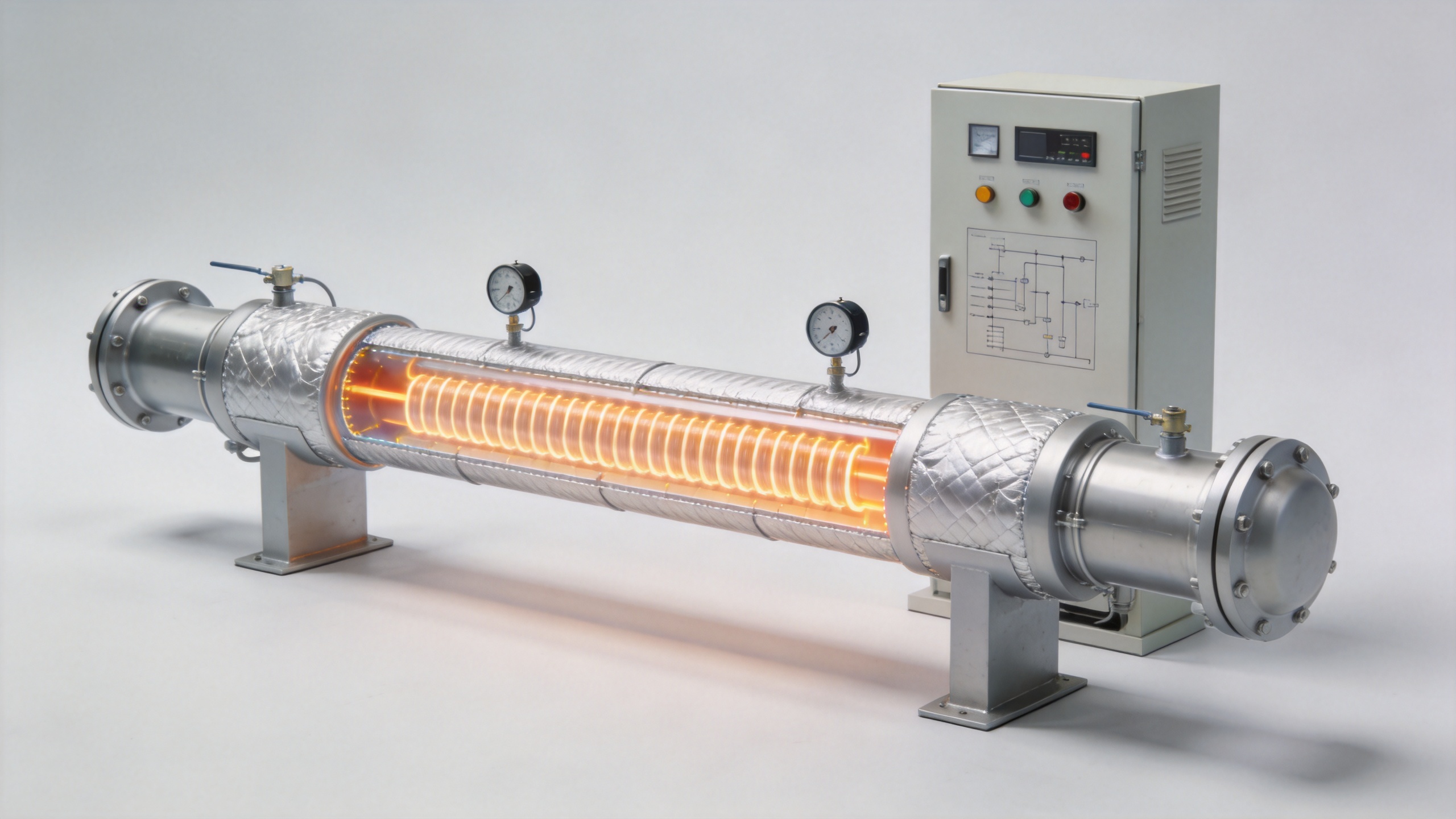
Pipe heating versus a process heat exchanger
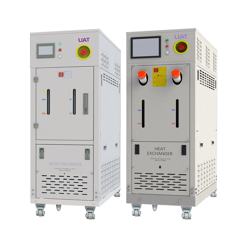
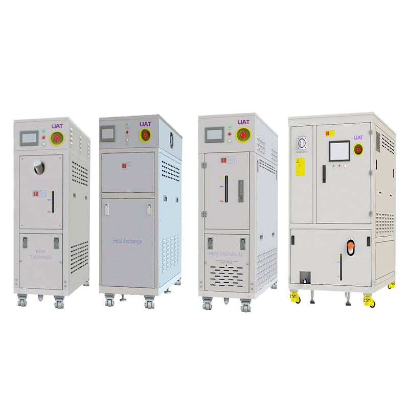
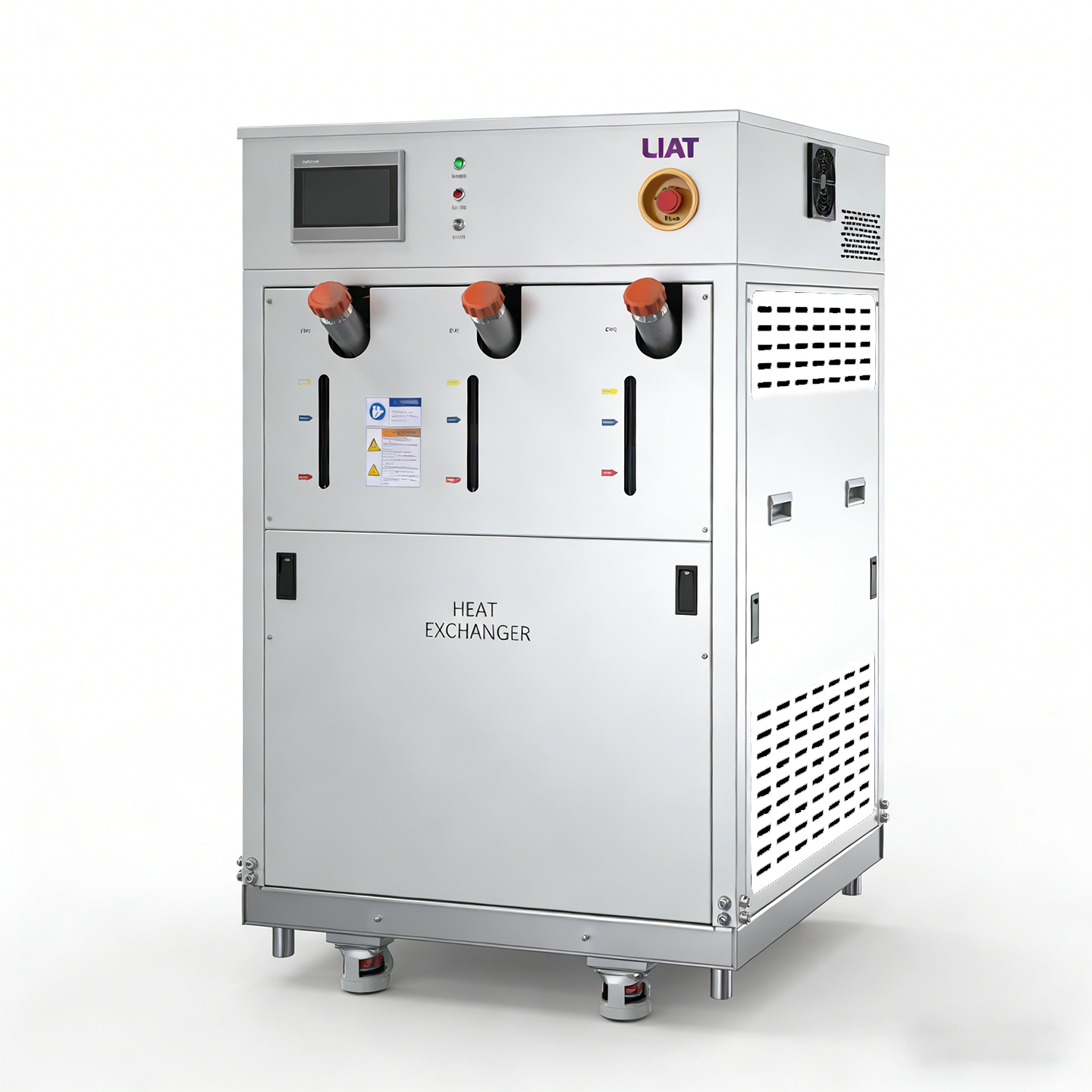
A process heat exchanger is usually chosen to raise or remove heat from the bulk stream at a defined point. It may set the starting condition, but it does not by itself guarantee that the condition survives downstream. A pipe heating system addresses distribution losses and local gradients after that upstream step.
| Question | Bulk heat exchanger | Distributed pipe heating |
|---|---|---|
| Primary task | Change bulk-stream temperature | Maintain a validated temperature profile along the run |
| Primary review point | Heat duty, inlet/outlet conditions, compatible wetted path | Cold spots, sensor locations, insulation, heat-loss zones, controls |
| Common blind spot | Assuming outlet temperature represents the tool inlet | Assuming surface temperature proves fluid temperature |
Many etch systems need both functions. The design decision should start with the fluid’s approved temperature range, expected flow profile, line length, ambient conditions, permitted materials, and cleaning requirements. With those facts in hand, the team can decide whether a heat exchanger, a heating jacket, or both are appropriate.
A practical investigation sequence for recurring deposits
- Define the symptom. Record deposit location, appearance, time since cleaning, pressure trend, flow condition, and whether the event follows idle time, recipe changes, or maintenance.
- Map the thermal profile. Compare representative locations during startup, normal flow, low flow, and idle periods. Include fittings, supports, valve bodies, and terminal sections rather than only easy-to-reach straight pipe.
- Verify the fluid and process conditions. Check approved chemistry concentration, filtration status, mixing or dilution steps, exposure to contamination, and the process team’s validated temperature limits.
- Check the control architecture. Confirm sensor identity, calibration status, alarm logic, controller response, heater zoning, and what happens after a power interruption or no-flow period.
- Inspect the physical installation. Look for insulation gaps, compressed or damaged heating media, unsupported runs, inaccessible inspection points, and changes introduced during service.
- Validate the correction. After a change, monitor the same points across the duty cycle and correlate them with pressure, flow, and residue observations. Do not treat a clean line after one short run as conclusive proof.
Design and operating details that matter
Uniformity is usually more valuable than aggressive heating. A high setpoint cannot compensate for incomplete coverage, slow control response, or an unverified temperature sensor. Similarly, insulation is a system component, not an afterthought: it reduces heat loss, lowers the workload on the heater, and makes the delivered condition less sensitive to room changes.
Materials and serviceability are equally important. Confirm compatibility of the pipe, seals, jacket, adhesives, insulation, sensors, and cleaning approach with the actual chemistry and temperature range. Plan access for inspections and replacement without creating unheated gaps. If the line crosses different zones, define who owns the setpoint, alarms, and change record so that a local adjustment does not unintentionally alter the process condition elsewhere.
Questions to settle before selecting or modifying equipment
- What fluid condition is validated at the tool inlet, and how is it measured?
- What are the maximum line length, fitting density, ambient exposure, and idle duration?
- Which locations have shown deposits, drift, or pressure changes?
- Which wetted and external materials have been approved for the chemistry and cleaning procedure?
- What is the required response when flow stops, power cycles, or an alarm occurs?
- What evidence will demonstrate that the corrected thermal profile is repeatable?
Conclusion
A pipe heating system can reduce solid-buildup risk in etch lines by maintaining a controlled thermal profile instead of relying on the bulk temperature alone. The most reliable approach combines a validated process window, properly zoned heating, insulation, meaningful measurement points, and a disciplined verification plan. For a particular line, begin with the observed deposit location and the real operating cycle, then evaluate temperature alongside chemistry, flow, materials, and control behavior. That approach makes a heating jacket or process heat exchanger a defensible part of process control rather than a guess at the cause of buildup.
 Hot News