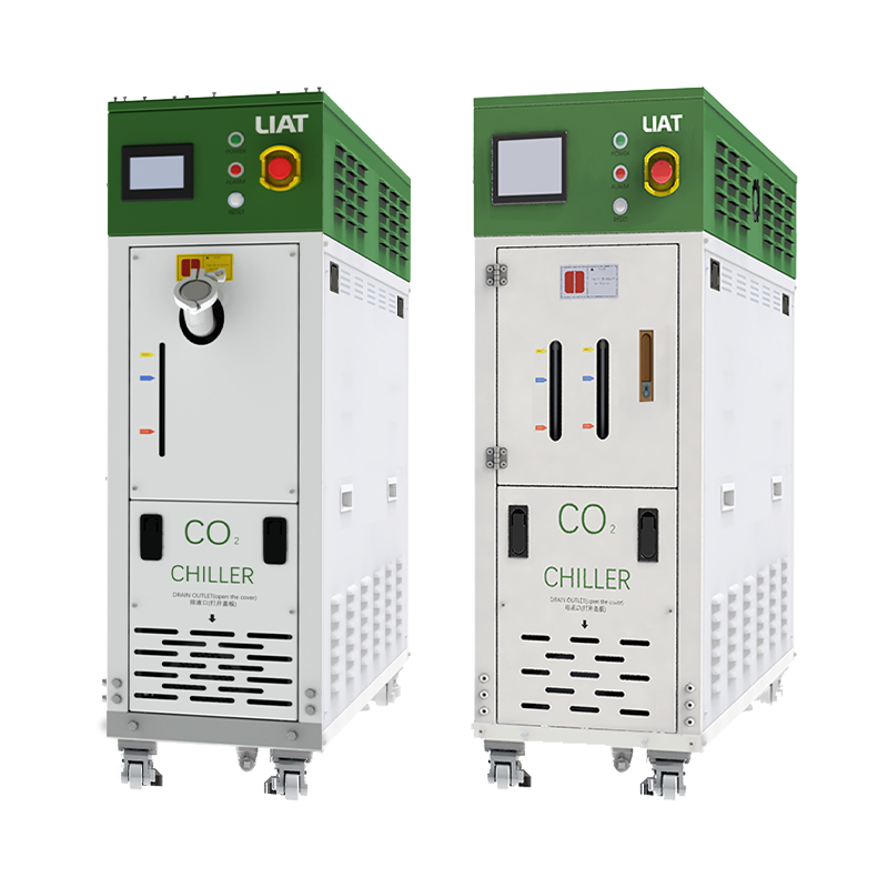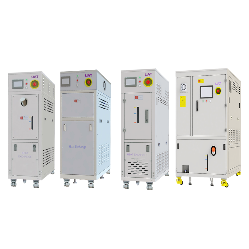


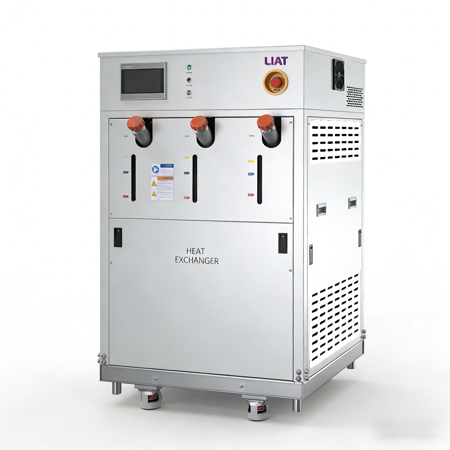
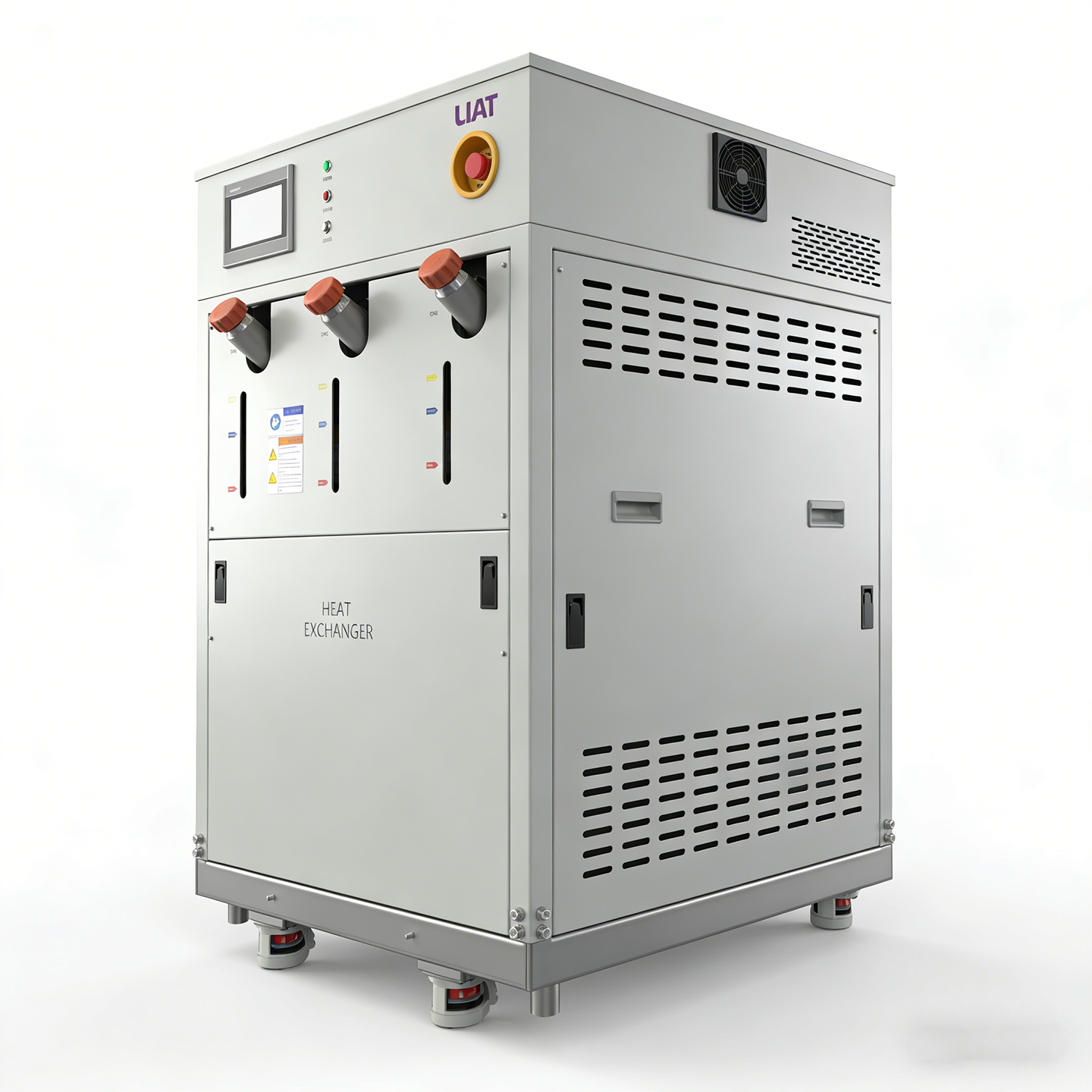
Triple Channel Heat Exchangers
Temperature Accuracy (Idle): ±0.2 ℃
Temperature Range:
Channel 1 & 2: +40°C to +180°C
Channel 3: +30°C to +80°C
Advanced PLC control with PID algorithms achieves ±0.2℃ precision temperature regulation of process fluid. This system is deployed across critical thermal management scenarios:
Semiconductor manufacturing equipment
New energy testing platforms
Medical diagnostic devices
Industrial laser systems
- Overview
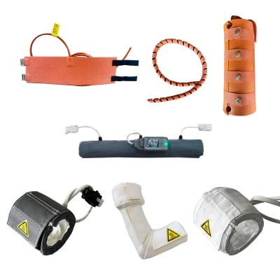
- Recommended Products
1.Heat Exchange Capacity:
Channel 1 & 2: 6 KW @+50°C / 21 KW @+100°C / 36 KW @+150°C
Channel 3: 16 KW @+70°C
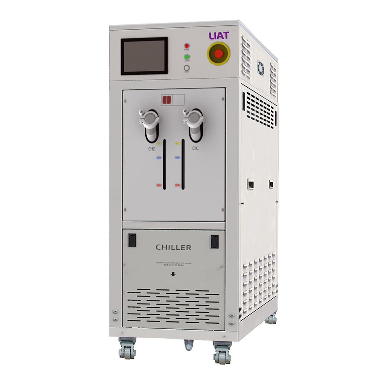
This system features three independent temperature control circuits, utilizing 3-way valve (CH1&2) and 2-way valve (CH3) PID control to achieve high-precision, independent thermal management for multiple process fluids. It is ideally deployed in complex thermal management scenarios such as semiconductor manufacturing, new energy testing, medical equipment, and industrial laser systems.
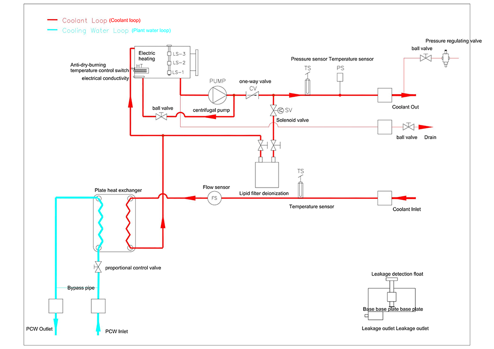
2. Technical Description
The Lingheng triple-circuit heat exchanger is equipped with a 7-inch HMI touchscreen featuring an intuitive fully Chinese interface. It enables clear parameter visualization, real-time temperature trend graphing, and storage of over 5000 fault records for easy operation, monitoring, and maintenance diagnostics. The user interface is fully customizable to meet specific customer needs.
For communication, the device employs a standard RS485 port compliant with the Modbus-RTU protocol. It reliably transmits over 18 critical data points—including outlet fluid temperature (±0.2℃ accuracy), equipment fault codes, real-time flow rates, and system status alerts—to superior SCADA/MES systems for intelligent monitoring and control.
3. Key Advantages
Triple-Circuit Integration: One unit simultaneously manages three independent process loops, significantly enhancing equipment integration and space utilization.
High-Efficiency Plate Heat Exchanger: Utilizes copper-brazed/nickel-brazed stainless steel plate heat exchangers with optimized internal turbulent flow, offering high thermal efficiency, low fouling impact, and second-level temperature response.
Powerful Heat Transfer Capacity: Compressor-free design delivers up to 36KW of heat transfer at 150°C for Channels 1 & 2, meeting demanding high-temperature, high-load process requirements.
Deep Communication Compatibility: Supports multiple industrial protocols (e.g., SECS/GEM, OPC UA) alongside standard Modbus-RTU for plug-and-play integration with leading semiconductor tools from AMAT, LAM, TEL, etc.
Comprehensive Safety Protection: Incorporates a multi-level safety system with over ten monitoring and protection functions (Warning & Alarm) covering level, flow, temperature, pressure, and leak detection, ensuring safe and stable operation of both equipment and process.
4. Principle Comparison with Traditional Equipment
Characteristic |
Plate Heat Exchanger (This Product) |
Shell-and-Tube Heat Exchanger |
Heat Transfer Driving Force |
High ΔT gradient + intense turbulence |
Primarily relies on temperature difference |
Flow Path |
Multi-channel parallel flow |
Single-path serpentine flow |
Fouling Impact |
Low fouling resistance |
Prone to scaling |
Temperature Response |
Second-level regulation |
Minute-level response |
Compactness |
Compact structure, high surface area per unit volume |
Relatively bulky |
5. Key Specifications Summary
Process Fluid: Channel 1 & 2: JHT 270; Channel 3: 60% EG or DI Water
Reservoir Capacity: 50L independent reservoir per channel (CH3 includes an 18L DI tank)
Heater Power: Channel 1 & 2: 12KW; Channel 3: 6KW
Pump: Channel 1 & 2: Magnetic Drive Pump (Variable Frequency, 2.2KW); Channel 3: Horizontal Centrifugal Pump (Variable Frequency, 1.2KW)
Safety Devices: Includes low/high level warnings, high/low temperature alarms, flow anomalies, leak detection, EMO stop, etc.
Communication Interface: RS485 (Modbus-RTU)
Power Supply: 190–230 VAC, 3-phase, 50/60 Hz, Rated Power 36.1 KW, Max. Current 100.3A
Dimensions (Overall): Approx. 750–800 (W) x 900 (D) x 1350 (H) mm
Certifications/Standards: Complies with SEMI S2, F47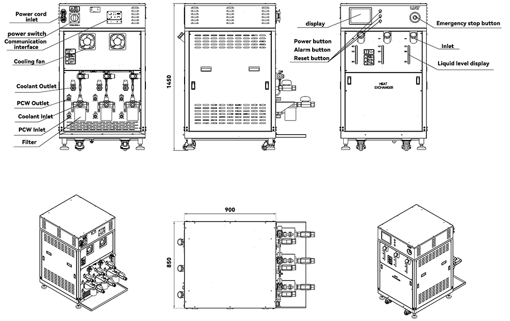
| Heat Exchange HPT030-W-32-2F2/W-R2-AN-ZW | |||||||
| Channelaisle | Channelaisle 1 | Channelaisle 2 | Channelaisle 3 | ||||
| Temperature rangeTemperature range | +40°C to +180°C | +40°C to +180°C | +30°C to +80°C | ||||
| Fluidfluid | JHT 270 | JHT 270 | 60% EG,DI Water | ||||
| Tankwater tank | 50 L | 50 L | 50 L | ||||
| Temperature accuracy (( idle )Static control accuracy | ± 0.2℃ | ± 0.2℃ | ± 0.2℃ | ||||
| Temperature controlTemperature control method | 3-way valve PID control | 3-way valve PID control | 2-way valve PID control | ||||
| Heat exchangerheat exchanger | Cooling capacityHeat exchange | 6 KW @+50°C 21 KW @+100°C 36 KW @+150°C | 6 KW @+50°C 21 KW @+100°C 36 KW @+150°C | 16 KW @+70°C | |||
| PCWCooling water | 15 LPM @15~ 25℃ | 15 LPM @15~ 25℃ | 15 LPM @15~ 25℃ | ||||
| Heat exchangerHeat exchanger type | Plate heat exchangerCopper brazing stainless steel plate replacement | Plate heat exchangerCopper brazing stainless steel plate replacement | Plate heat exchangerNickel-welded stainless steel plate replacement | ||||
| Heaterheater | 12 KW (4 KW x 3)Or 6 KW x 2) | 12 KW (4 KW x 3)or6 KW x 2) | 6 KW (3 KW x 2) | ||||
| DI Tank Deionizer | NA | NA | 18 L | ||||
| Pumpwater pump | Pumptype | Magnetic pump (frequency conversion) | Magnetic pump (frequency conversion) | HorizontalCentrifugal pump (variable frequency) | |||
| Powerpower | 2.2 KW, IE2 | 2.2 KW, IE2 | 1.2 KW | ||||
| Pump capacityability | 30 LPM @0.5MPa | 30 LPM @0.5MPa | 20 LPM @0.5MPa | ||||
| Safety devicesEquipment safety | WarningWarning (no shutdown) | 1.The circulating fluid tank is at a low level, indicating the need to add fluid. | Reservoir Low Level WRN | ||||
| 2.High liquid level in circulating fluid tank | Reservoir High Level WRN | ||||||
| 3.The circulating fluid temperature has not reached the set value. | Reservoir Low temp. WRN | ||||||
| 4.The circulating fluid flow rate is lower than the customer's set value. | Circulating fluid Low Flow WRN | ||||||
| 5.The temperature of the circulating fluid return is higher than the specified value. | Circulating fluid Return High Temp. WRN | ||||||
| AlarmAlarm (Power Off) | 1.There is a leak in the chassis. | Water Leak Detect FLT | |||||
| 2. EMOEmergency Stop | EMO emergency stop FLT | ||||||
| 3.Power phase sequence error | Incorrect Phase Error FLT | ||||||
| 4.Low liquid level in circulating fluid tank | Reservoir Low Level FLT | ||||||
| 5.Overheat protection action of circulating fluid tank | Reservoir High Temp. FLT | ||||||
| 6.Water pump frequency converter failure | Pump Inverter Error FLT | ||||||
| 7.The water pump is constantly operating at high or low pressure. *(Higher than 1.0 MPaBelow0.1 MPa | Pump high/low pressure FLT | ||||||
| 8.Low circulating fluid flow rate*(Below3L/min) | Circulating fluid Return Low Flow FLT | ||||||
| 9.Circulating pump circuit breaker protection | Pump Breaker Trip FLT | ||||||
| 10.The outlet temperature of the circulating fluid exceeds the specified value. | Circulating fluid High Temp. FLT | ||||||
| 11.Temperature sensor malfunction | Temperature sonsor error FLT | ||||||
| Piping sizeInlet and outlet dimensions | Fluidmedium | Return | RC 3/4" x 2 | RC 3/4" x 2 | RC 3/4" x 2 | ||
| Supply | RC 3/4" x 2 | RC 3/4" x 2 | RC 3/4" x 2 | ||||
| PCWCooling water | Return | RC 1/2" | RC 1/2" | RC 1/2" | |||
| Supply | RC 1/2" | RC 1/2" | RC 1/2" | ||||
| Dry Airdry air | Inlet | Φ6mm | |||||
| Power connection | Connector (Female)Claw cable fastening connector125A (3P+PE)(Cable end female) P/N: TYP2719(125A/IP67) Clamping cable fix plug(Male)Claw cable fastening plug125A (3P+PE)(Male connector for device) P/N: TYP973(125A/IP67) | ||||||
| EMO AMPConnector definition | EMO AMPGeneral4Core socket 206430-1(Four-needle round mouth) with female head | AMPdefinition:pin2,pin3It is an emergency stop alarm. | |||||
| Bottom overflow tray drainChassis drain port | RC 1/2" with Plug Cap | ||||||
| Empty out drainSystem medium drain port | 1/2" Ball Valve with Plug Cap | 1/2" Ball Valve with Plug Cap | 1/2" Ball Valve with Plug Cap | ||||
| CertificationCertification and Standards | SEMI S2, F47 | ||||||
| Interfacecommunication | RS 485 | ||||||
| Rated PowerRated power | 36.1 KW | ||||||
| Maximum CurrentMaximum current | 100.3 A | ||||||
| Average CurrentaverageCurrent | 36.3A *This data represents the simulated circulating fluid temperature.@+25˚ CElectric heating output ratio 20% | ||||||
| BreakerMolded case circuit breaker | 125A(Schneider EZDseries) | ||||||
| Dimensions (overall) | 750~800W*900D*1350H(Preliminary estimate) | ||||||
| Power supplypower supply/power | 190~ 230 VAC, 3ø, 50Hz / 60Hz | ||||||