How Does a Heat Exchanger Work for Industrial Cooling?
In industrial cooling, a heat exchanger moves heat away from a process without allowing the two working fluids to mix. That simple task is central to temperature control, but its real performance depends on the temperature difference, flow conditions, available surface area, fluid cleanliness, and pressure drop. From a thermal-management application engineer’s perspective, the useful starting point is not a model number. It is the heat load, target temperature range, and fluid conditions the system must handle.
A heat exchanger may sit between process equipment and a chilled-water loop, between a cooling tower circuit and a machine loop, or inside a packaged temperature-control system. In every case, it provides a controlled path for thermal energy to leave the warmer side and enter the cooler side.
The Basic Heat Exchanger Principle
A heat exchanger has two fluid paths separated by a solid wall. One fluid is warmer; the other is cooler. Heat follows the temperature difference: it convects from the warm fluid to the wall, conducts through the wall, and convects from the wall into the cooler fluid. The fluids can remain physically separate, which is important when a process fluid must not be diluted or contaminated by plant cooling water.
The temperature difference is the driving force. When the difference between the two streams becomes smaller, the same duty usually requires more heat-transfer area, a different flow arrangement, or changes in flow conditions. Engineers often use the log mean temperature difference (LMTD) to represent the average driving temperature difference across a heat exchanger. It is a calculation tool, not a promise of performance: actual results still depend on fluid properties, fouling, flow distribution, and the installation.
What Happens in an Industrial Cooling Loop?
Consider a machine that releases heat into a recirculating process-water loop. The warm return fluid enters one side of the heat exchanger. A colder utility fluid enters the other side. As both streams travel through their assigned channels, thermal energy crosses the separating wall. The process fluid leaves cooler and returns to the machine; the utility fluid leaves warmer and carries that heat toward a chiller, cooling tower, dry cooler, or another rejection point.
Energy is not created or destroyed in the exchanger. The heat removed from one stream must be accepted by the other stream, subject to losses and transient storage in the equipment. That is why heat load and expected inlet and outlet temperatures should be confirmed together. If heat load information is incomplete, comparing exchanger sizes alone can lead to an unsuitable choice.
Common Configurations and Why Flow Arrangement Matters
Plate heat exchangers
Plate designs use thin corrugated plates to form many narrow flow channels. Their large effective surface area can support compact industrial cooling layouts. They are often considered where close temperature approach and service access matter, but channel geometry and water quality still need to match the operating conditions.
Shell-and-tube heat exchangers
In shell-and-tube equipment, one fluid flows through tubes while the other moves around them in the shell. This familiar arrangement can suit a wide range of fluids and duties. Its behavior depends on tube layout, baffles, velocity, materials, and the maintenance plan rather than on the configuration name alone.
Counterflow and parallel flow
Counterflow sends the two streams in opposite directions. It generally maintains a more useful temperature difference along the length of the exchanger than parallel flow, where both streams move in the same direction. The preferred arrangement depends on achievable approach temperatures, controllability, pressure-drop limits, and the broader cooling system.
How Engineers Estimate Heat Exchanger Duty
For a preliminary heat exchanger review, engineers connect the process heat load with the fluid flow rate and the temperature change expected on each side. They then compare that duty with the temperature driving force available along the unit. A heat exchanger with adequate area on paper can still miss the required outlet temperature if the utility supply is warmer than expected, flow is lower than designed, or deposits have raised thermal resistance.
This is why commissioning data should include temperatures and differential pressure on both circuits. Those measurements give the team a more useful picture of how the heat exchanger is performing than a single outlet-temperature reading.
Four Factors That Determine Cooling Performance
- Heat load: Start with the heat the process must reject, including normal operating load and realistic variation. A steady laboratory load and a cycling production load can demand different control strategies.
- Temperature approach: The closer the required process outlet temperature is to the utility inlet temperature, the less driving force is available. This can increase the required surface area or change upstream utility requirements.
- Flow rate and pressure drop: Higher velocity can improve convection, yet it also raises pumping demand and may exceed allowable pressure drop. The right balance is specific to the loop and its pump capacity.
- Fluid condition and fouling: Scale, corrosion products, biological growth, or particles add thermal resistance. A clean heat exchanger can behave very differently from the same unit after months of untreated service.
These factors are connected. For example, increasing flow may improve heat transfer but create an unacceptable pressure loss. More accurately, any conclusion about cooling capacity should be limited by the confirmed fluid, flow, temperature, and interface conditions.
When to Review the Heat Exchanger Design
Review the heat exchanger when production throughput changes, a process starts using a different fluid mixture, seasonal utility temperatures move outside the original assumption, or cleaning intervals become shorter. These changes can alter the driving temperature difference, viscosity, fouling tendency, and pumping requirement. Early review is usually less disruptive than waiting for a process-temperature alarm.
How to Think About a Heat Exchanger in a Chiller System
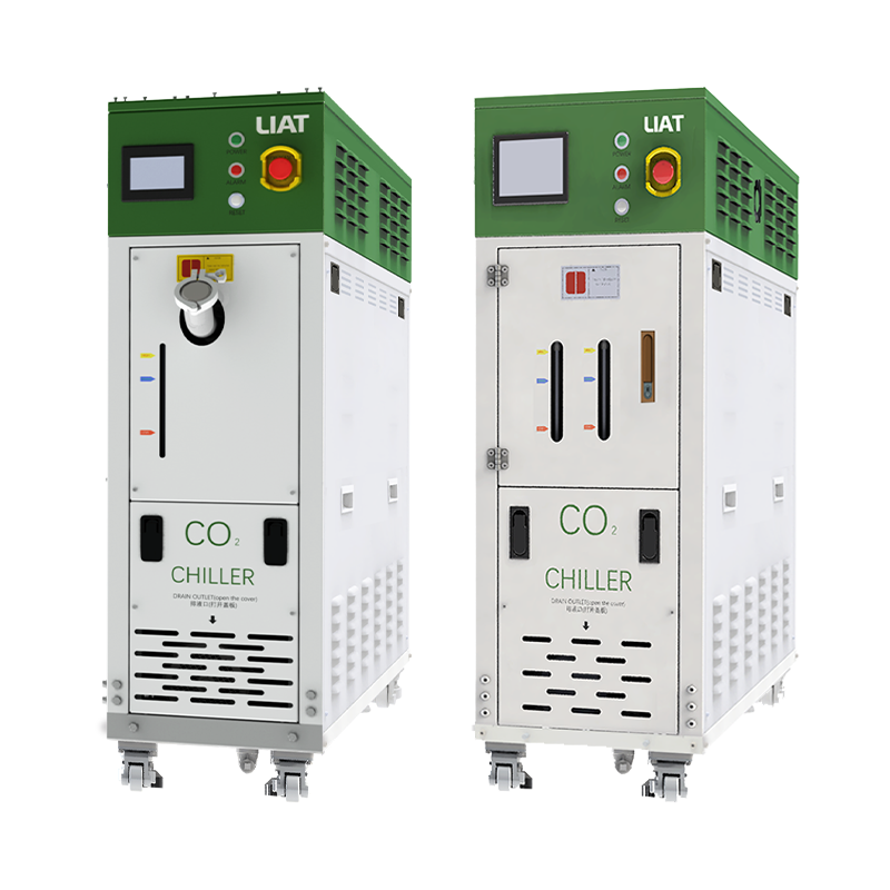
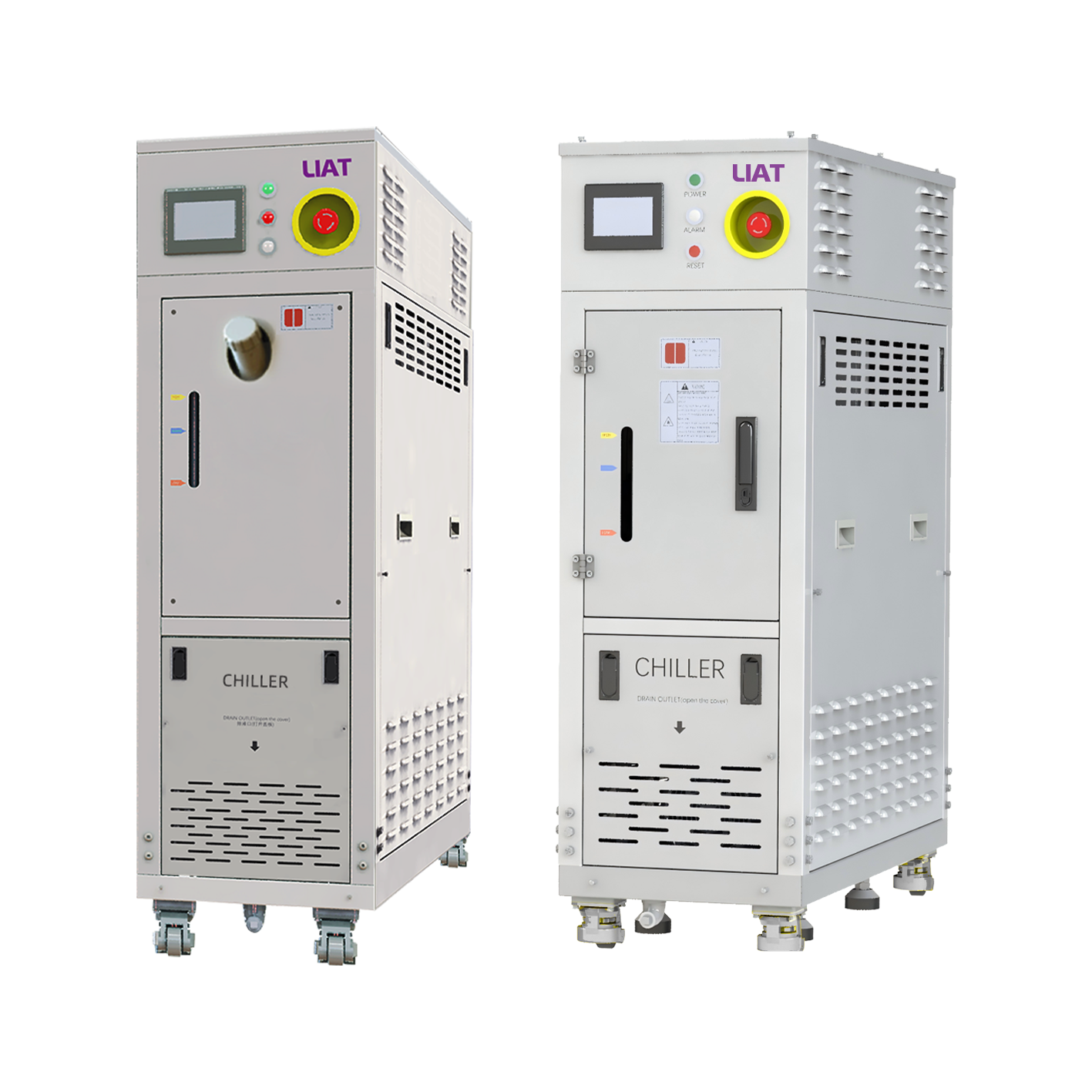
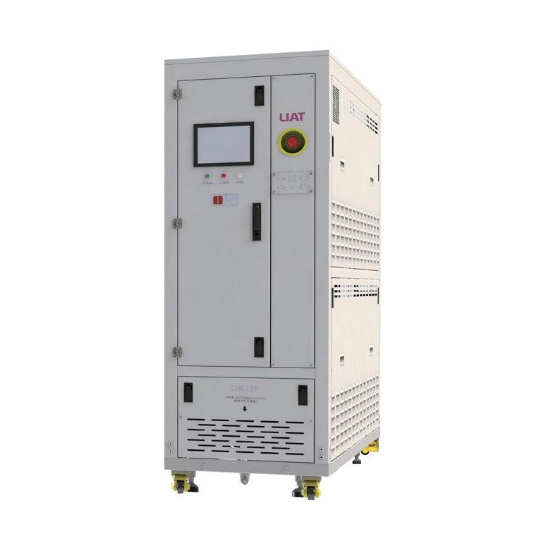
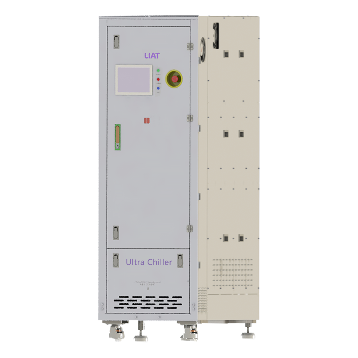
A heat exchanger does not replace the component that ultimately rejects heat. In a chiller-based system, it can isolate circuits, protect a sensitive process loop, accommodate different fluid chemistries, or transfer heat between a secondary loop and the refrigeration-side evaporator. The chiller must still remove the combined thermal load, while the exchanger must pass that duty at the available temperatures.
Before selecting equipment, clarify the process supply and return temperatures, utility supply temperature, minimum and maximum heat load, permissible pressure drop, fluid composition, contamination risk, and required control response. Discussing the heat load, temperature range, and medium first is more useful than rushing to compare individual specifications. It also helps define whether a water-to-water, water-to-glycol, or another arrangement is appropriate.
Practical Checks for Operation and Maintenance
- Trend inlet and outlet temperatures on both sides, rather than relying on a single process temperature.
- Monitor differential pressure; a rising value can indicate blockage or fouling.
- Verify that pumps and valves deliver the intended flow under actual operating conditions.
- Review water treatment and filtration practices where the fluid can form deposits.
- Inspect seals, connections, and isolation valves according to the equipment design and site procedures.
- Recheck performance after process changes, because a new product, cycle time, or ambient condition can alter the cooling duty.
These checks do not diagnose every issue, but they make it easier to distinguish a heat-transfer limitation from a control, pump, or utility problem. A measured approach is preferable to treating any temperature drift as proof that the exchanger alone has failed.
During this review, the heat exchanger should be evaluated with the full cooling loop, including the process load, utility source, pumps, controls, and service plan. A heat exchanger that is correctly matched to its actual duty helps maintain stable process conditions.
Frequently Asked Questions
Do the fluids mix inside a heat exchanger?
Normally, no. A separating wall keeps the two fluids apart while heat passes through it. The exact construction and integrity requirements depend on the application and fluids involved.
Can a heat exchanger cool below the utility-fluid inlet temperature?
Not in a simple sensible heat-transfer arrangement. The available temperature difference sets a boundary. Reaching a lower process temperature requires a colder utility source or a different cooling process.
Why does fouling reduce cooling capacity?
Deposits act as an added insulating layer. They reduce the rate at which heat crosses the wall and can also restrict flow, increasing pressure drop.
Key Takeaway
A heat exchanger works by transferring thermal energy from a warmer industrial process fluid to a cooler utility fluid across a separating wall. Reliable industrial cooling comes from matching that mechanism to the real duty: heat load, temperatures, flow, fluid condition, pressure-drop limits, and maintenance needs. When those inputs are confirmed, the exchanger can be evaluated as part of the complete cooling loop instead of as an isolated component.
 Hot News