Why a Vacuum Line Heating Jacket Prevents Cold Spots
In a temperature-sensitive vacuum process, a line is not simply a path between two components. It is part of the process environment. A local temperature drop at a valve body, clamp, support, bend, or exposed transition can change the condition of material moving through the line. That is why engineers often evaluate a vacuum line heating jacket as part of the whole thermal path rather than as an isolated accessory.
From a process-risk perspective, cold spots deserve attention because they can create a location where vapors cool sooner than intended. Depending on the chemistry and operating window, that may increase the chance of condensation, deposition, viscosity change, or an unstable delivery condition. A vacuum line heating jacket does not replace process qualification, but it can help maintain a more consistent line temperature when it is specified, installed, and verified against the actual duty.
What Counts as a Cold Spot in a Vacuum Line?
A cold spot is a section whose surface or fluid-path temperature sits below the intended thermal profile. One controller display may not reveal it. The controlled zone may read correctly while a short, unheated section near a fitting loses heat to surrounding air, a mounting bracket, or adjacent equipment.
In practical reviews, the usual suspects are not only straight pipe runs. They include:
-
Valves, tees, reducers, elbows, and instrument connections;
-
Flange faces and clamps where jacket coverage stops too early;
-
Metal supports that conduct heat from the line;
-
Access panels opened during maintenance or exposed to drafts;
-
Sensor locations that do not represent the coolest part of the run; and
-
Transitions between a heated line and an unheated chamber or source connection.
The key point is simple: a temperature setpoint is not the same as a temperature map. If the process has a narrow acceptable range, the map matters.
How a Vacuum Line Heating Jacket Helps
A vacuum line heating jacket adds controlled heat around a defined section of line. With insulation and appropriate coverage, it can reduce the temperature difference between the center of a long run and its more exposed sections. The goal is not to make every surface identical at all times. The goal is to keep the real temperature profile within the operating conditions defined for the process.
That distinction matters. Heat loss varies with line material, diameter, geometry, nearby equipment, airflow, insulation condition, and ambient temperature. An industrial heating jacket should therefore be matched to the line geometry and the thermal duty, not selected from a nominal temperature rating alone.
Relevant gas-delivery guidance also describes uniform thermal barriers as a way to address locations where condensation can begin. This is a useful engineering principle, not a universal outcome claim. The actual benefit still depends on the material being conveyed, the required temperature, the control method, and verification during commissioning.
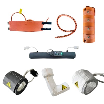
Illustrative view of controlled heating and insulation around a process-line assembly.
Why Temperature Uniformity Matters to Process Stability
For vacuum and semiconductor-adjacent applications, the concern is often not just comfort or surface warmth. Process materials may be sensitive to temperature changes along the delivery route. If a vapor cools near a connection, the resulting change can affect transport behavior before the material reaches its destination. In some processes, residue or condensed material can also complicate cleaning and maintenance planning.
A well-considered vacuum line heating jacket supports a more repeatable thermal environment by limiting avoidable heat-loss zones. It is especially useful when a line passes through a cooler enclosure, crosses an open service area, or contains several fittings with different thermal masses. Still, the jacket is one part of the system. Insulation, sensor placement, controller settings, power distribution, cable routing, and mechanical access must work together.
Common Reasons Heating Jacket Installations Still Develop Cold Sections
-
Coverage ends at the wrong place: A jacket may cover the long straight section while leaving an elbow, valve, or transition exposed. This can be enough to create a local drop in temperature. Before extending coverage, confirm maintenance access and the safe temperature limits of nearby seals, instruments, and cables.
-
Sensor placement hides the problem: A control sensor mounted in a favorable location can report a stable value even when another section is cooler. For a critical vacuum line heating jacket installation, it is often helpful to use temporary measurements during commissioning at suspected low-temperature locations. The objective is to compare conditions, not to assume that one sensor represents every component.
-
Insulation and support details are treated as secondary: An industrial heating jacket may provide useful heat input, but exposed joints, compressed insulation, and conductive metal supports can still change the thermal balance. Review the full assembly after the jacket is installed. Look for gaps, compression points, exposed hardware, and areas where the line touches a cooler structure.
-
The operating case changes after setup: Warm-up time, material flow, ambient conditions, and adjacent equipment loads may differ between commissioning and production. A setting that looks suitable during a short test may need adjustment after the system reaches steady duty. This is why a conditional review is more useful than relying on a single nominal value.
A Practical Specification Checklist
When assessing a vacuum line heating jacket, organize the conversation around the process rather than a catalog label. The following checklist helps bring missing conditions into view:
-
Define the thermal objective: identify the temperature range and where it applies along the line.
-
Map the geometry: include straight lengths, elbows, valves, tees, flanges, supports, and transitions.
-
Identify the conveyed medium: confirm its temperature sensitivity and any known deposition or condensation concerns with the process owner.
-
Review surrounding conditions: note enclosure airflow, ambient changes, adjacent cold surfaces, and access requirements.
-
Plan control and sensing: define controller location, sensor positions, alarms, and what happens after power interruption.
-
Check materials and interfaces: verify that jacket, insulation, fasteners, seals, and electrical interfaces suit the site conditions.
-
Set an acceptance method: use measured locations and a defined warm-up or steady-state condition to verify the thermal profile.
This approach is also useful for procurement teams. Instead of comparing products only by wattage or maximum temperature, they can request a clear response to the line layout, target range, medium, controls, and service constraints.
Commissioning: Verify the Line, Not Just the Controller
A sensible commissioning plan starts with visual inspection. Confirm coverage, fastening, electrical routing, insulation continuity, and access to critical components. Then bring the system to the intended operating condition and take measurements at the places most likely to lose heat: fittings, supports, terminal ends, and transitions.
Record the controller setpoint, measurement locations, ambient conditions, warm-up period, and observed temperatures. If a difference appears, trace it back through coverage, sensor location, heat loss, and mechanical contact before changing the setpoint. Raising a setting may mask a local issue while creating unnecessary heat elsewhere.
For organizations managing semiconductor thermal-control, chemical, or advanced manufacturing equipment, this evidence-based routine makes later maintenance decisions easier. It also separates confirmed observations from assumptions, which is valuable when process owners, maintenance staff, and equipment integrators need to coordinate.
Choosing the Right System Partner
For a critical application, the useful discussion is usually broader than the jacket itself. Lingheng Thermal Control Technology (Suzhou) Co., Ltd. works in precision temperature-control and thermal-management equipment for industrial applications. A productive project discussion should start with the target temperature range, heat load, medium, line geometry, control interfaces, and maintenance conditions. Those details help define a solution path that can be evaluated against the actual installation rather than an assumed “typical” line.
Ask potential suppliers to clarify the information needed for configuration, the intended control approach, installation boundaries, and how the assembly can be verified on site. A transparent answer is more useful than an unqualified promise, particularly when the vacuum line affects a sensitive process.
Conclusion
A vacuum line heating jacket helps address cold-spot risk by supporting a more controlled thermal profile across a process line. Its value comes from matching coverage, insulation, controls, sensing, and verification to the actual duty. When the line is reviewed as a system—including fittings, supports, transitions, and operating changes—teams can identify where heat loss is most likely and build a more defensible commissioning plan.
 Hot News