
Why Pipe Heating System Uniformity Matters for Thin-Film Deposition
In thin-film deposition, temperature control is often discussed at the chamber or substrate. Yet the path to the chamber can matter just as much. A pipe heating system that holds a stable setpoint but develops hot and cool sections along a precursor or process line can introduce a variable before material reaches the deposition zone. For equipment teams, the useful question is not simply “Is the line heated?” It is whether the thermal profile is uniform enough for the chemistry, flow path, and operating sequence that have been specified.
That distinction is especially important where vapors must remain stable from a source vessel to a chamber. A uniform pipe heating system helps keep the thermal environment repeatable; it does not, by itself, prove process performance. The process window, precursor data, insulation, tubing geometry, sensors, controls, and validation method still need review as one system.
Uniformity is a process-control issue, not a cosmetic specification
Thin-film methods differ, but many share one practical sensitivity: temperature affects how material is transported, arrives at a surface, and behaves during deposition. Technical guidance on vapor delivery commonly describes maintaining an appropriate positive temperature gradient from source toward chamber to reduce condensation risk. The exact profile depends on the precursor and tool design. Still, the principle is useful: unintended cold spots can be as consequential as a poorly chosen setpoint.
When a pipe heating system is nonuniform, a line may contain sections that are cooler than the controller display suggests. Vapor can lose energy at fittings, valve bodies, bends, uninsulated supports, or transitions between heater zones. Depending on the material, that may contribute to condensation, altered delivery behavior, deposits in the line, or inconsistent exposure from cycle to cycle. The reverse condition deserves equal care. Raising every zone indiscriminately is not a fix, because some process chemicals can have upper temperature limits or decomposition concerns.
Put differently, the target temperature is not the whole story. The condition that matters is the thermal path between source, delivery line, and chamber interface. A practical pipe heating system review maps that path before comparing heater ratings.
How temperature variation can appear in deposition results
A thin film is evaluated through properties such as thickness consistency, composition, adhesion, morphology, coverage, or electrical and optical behavior. A temperature gradient in a delivery path is rarely the only explanation for a change in those results, but it can be an upstream contributor worth isolating. If mass transport or precursor availability changes from run to run, downstream adjustments may mask the issue rather than remove it.
Consider a routine where a pipe heating system reaches its displayed setpoint before a run. If one valve cluster or metal flange remains cooler than the surrounding line, it may require more time to equilibrate. During short or intermittent sequences, that local difference may be more relevant than the average line reading. This is why the pipe heating system should be assessed across the actual routing, not only at a single control sensor.
- Cold spots may increase the chance of condensation or adsorption where the process chemistry is sensitive to temperature.
- Hot spots can create a different risk: excessive thermal exposure for materials, seals, or components not intended for that local condition.
- Zone-to-zone differences can make warm-up behavior and maintenance observations harder to interpret.
- Unverified gradients can complicate root-cause work when film results drift even though the nominal setpoint has not changed.
None of these points establishes a universal tolerance. The acceptable range must come from the process owner’s chemistry, source conditions, line materials, and qualification plan. That boundary is why pipe heating system uniformity deserves explicit measurement instead of a generic claim.
Where a pipe heating jacket fits into the system
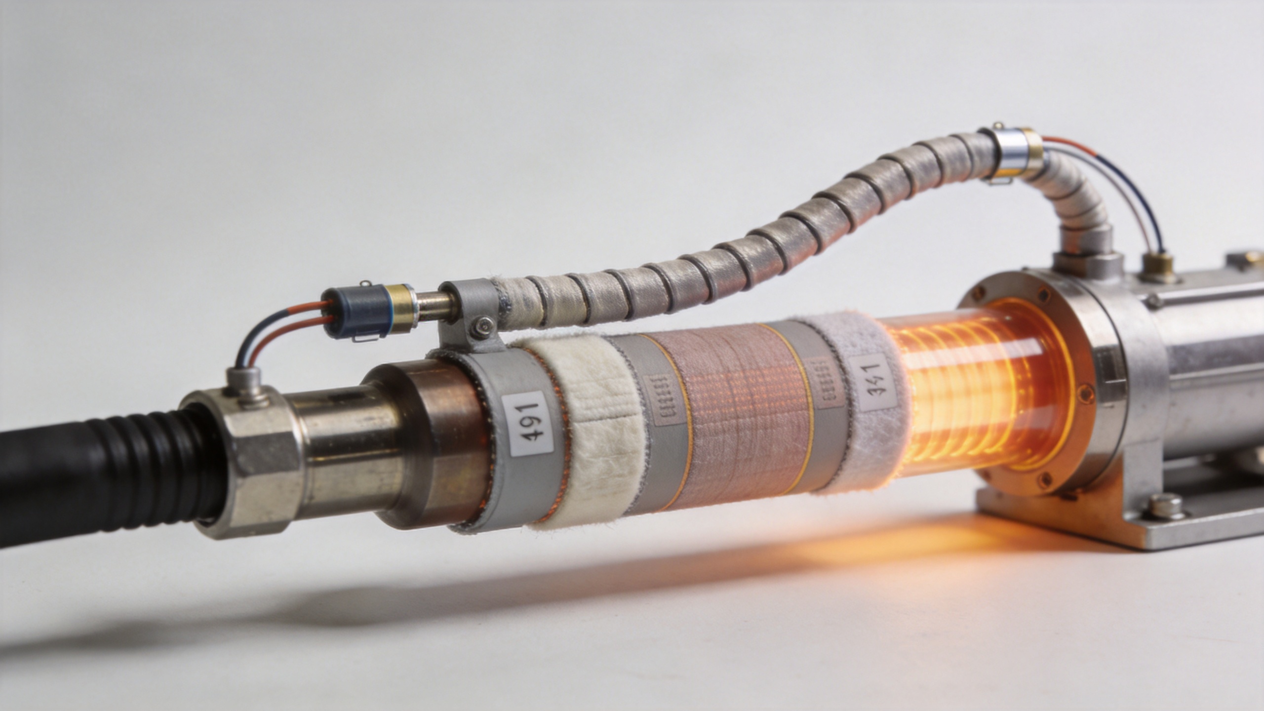
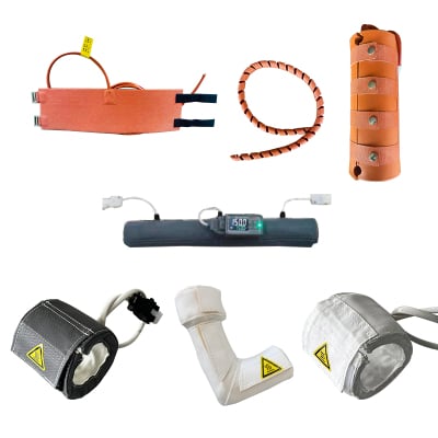
A pipe heating jacket can be a practical way to apply heat around tubing, piping, or selected components, particularly where geometry or retrofit constraints make rigid heating less convenient. But jacket selection should follow a line survey. Diameter changes, valves, fittings, support contact points, sensor placement, and insulation gaps all influence the assembled temperature profile.
For a heated process line, the evaluation should ask how the pipe heating jacket interfaces with the pipe, how individual zones are controlled, and how heat loss is managed around discontinuities. A heating solution that looks uniform when laid out flat may behave differently after it is wrapped around bends and connected to field hardware. In practice, installation quality and sensor strategy can be as influential as heater construction.
For the same reason, an industrial heating jacket should be discussed with operating conditions rather than as an isolated product category. The required temperature range, ambient exposure, cleaning constraints, power availability, material compatibility, access for service, and control architecture set the useful design boundary. A vendor or integrator can then translate those conditions into a configuration that is reviewable and testable.
A verification plan for along-line uniformity
Before accepting a new or modified line, use a repeatable inspection sequence. The aim is to turn “uniform heating” from an assumption into an observable condition. A concise plan can include the following steps.
- Define the process window. Record the approved temperature conditions for the source, line sections, valves, and chamber interface. Identify which limits are chemistry-driven and which are equipment-driven.
- Map the physical path. Mark every straight run, elbow, fitting, valve, reducer, support, and transition. These are potential thermal discontinuities, not merely installation details.
- Locate control and verification points. A control sensor may regulate the pipe heating system, but additional temporary measurements may be needed to characterize the profile during commissioning.
- Check warm-up and steady state. Measure after normal warm-up and, if relevant, after the actual process sequence. A stable reading at one location does not establish stability elsewhere.
- Inspect insulation and mechanical contact. Gaps, loose coverage, compressed insulation, or heat sinks at clamps can change local heat loss.
- Document deviations and corrective actions. Use a map, time record, and defined acceptance criteria so later film investigations can distinguish delivery-line changes from chamber changes.
This approach also makes maintenance deliberate. A heating jacket should be checked after line modifications, sensor replacement, insulation work, or changes in recipe timing. The point is not to create unnecessary paperwork; it is to preserve the connection between a physical heating arrangement and a qualified deposition process.
Control design matters as much as heater placement
Uniformity depends on more than distributing watts around a pipe. Control zoning, sensor contact, response to ambient change, and the relationship between source and downstream zones all influence the result. An industrial heating jacket with digital control can make conditions easier to monitor, but a display value remains only one part of the evidence. A commissioning record should state what was measured, where it was measured, when it was measured, and under what operating state.
It is also useful to separate accuracy from uniformity. Accuracy asks whether a measured point is close to its intended target. Uniformity asks how much relevant points differ from one another. A pipe heating system can appear accurate at its controller while retaining a gradient at a fitting or branch. For thin-film deposition, both questions need answers because the process sees the whole delivery path.
Common mistakes when specifying a heating jacket
- Choosing a heating jacket from pipe diameter alone without documenting fittings, bends, valves, and thermal losses.
- Assuming a controller setpoint proves uniform conditions along the entire run.
- Adding heat to correct a cold spot without checking precursor stability and component temperature limits.
- Leaving sensor placement, commissioning measurements, and acceptance criteria undefined.
- Treating a pipe heating system as separate from the source, flow-control hardware, insulation, and chamber interface.
These issues are avoidable when the specification starts with process conditions. The same discipline helps when comparing a pipe heating jacket or industrial heating jacket: ask what evidence will show that the assembled system is behaving as intended, not just what temperature the product can reach.
Make uniformity a documented acceptance condition
For thin-film deposition, heating uniformity is valuable because it reduces one uncontrolled variable in the material-delivery chain. It can support repeatable warm-up, clearer troubleshooting, and better alignment between a qualified recipe and the hardware that delivers it. It should not be framed as a standalone guarantee of film quality. Deposition outcomes still depend on the complete process, including source behavior, pressure, timing, chamber conditions, substrate treatment, and recipe control.
The most useful next step is a joint review between process and equipment teams. Define the acceptable thermal profile, map the real line, identify measurement points, and establish how changes will be requalified. With those conditions in place, a pipe heating system becomes an engineered part of deposition control rather than an overlooked utility around the pipe.
 Hot News