
How a Battery Pack Test Cooling System Manages Pack‑Level Heat
At pack level, thermal testing is not just a question of making a battery cold. A battery pack test cooling system creates controlled boundary conditions around the pack’s thermal circuit so engineers can observe how the pack, its controls, and its plumbing behave through a defined duty cycle. From a thermal-management engineer’s perspective, the useful starting point is the heat load, temperature target, coolant medium, and connection conditions—not a single headline capacity number.
This matters because a battery pack experiences changing heat generation during charging, discharge, soak, and transition events. A test setup may need to remove heat, add heat, hold a stable inlet condition, or move between conditions at a programmed rate. The battery pack test cooling system therefore acts as an active thermal boundary for the pack rather than a passive accessory beside the test bench.
What the system is actually controlling
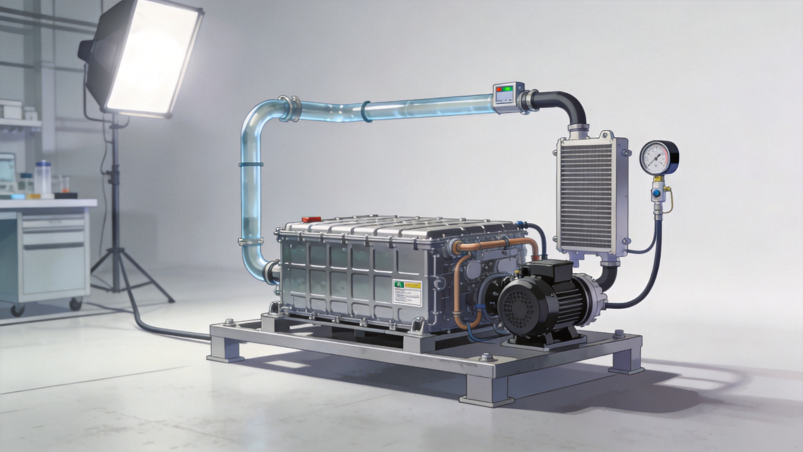
Most pack-level setups connect an external circulation loop to the battery’s coolant ports. The test unit conditions a heat-transfer fluid, moves it through the loop, and measures the response at the connection points. A well-planned battery pack test cooling system commonly controls or records inlet temperature, outlet temperature, coolant flow, loop pressure, and sometimes the temperature difference across the pack. Those signals are interpreted alongside pack voltage, current, state of charge, cell or module temperatures, and control messages from the test environment.
Temperature is only one part of the boundary condition. If flow is too low, a coolant inlet at the programmed temperature may not transport enough heat through the pack. If pressure or fluid properties are outside the intended test condition, the result can describe the external loop more than the pack itself. That is why engineers usually define a thermal profile as a coordinated set of conditions rather than a temperature setpoint alone.
How heat moves through the test loop
During a heat-rejection segment, heat generated inside the pack travels through cells, structural layers, and the cooling plate or other thermal pathway into the circulating fluid. The external unit receives warmer fluid at its return connection, rejects that heat, and sends fluid back at the programmed inlet condition. In a heating segment, the direction of useful heat flow is reversed: the test loop delivers conditioned fluid that helps bring the pack toward the required state.
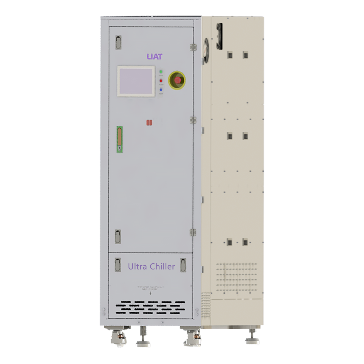
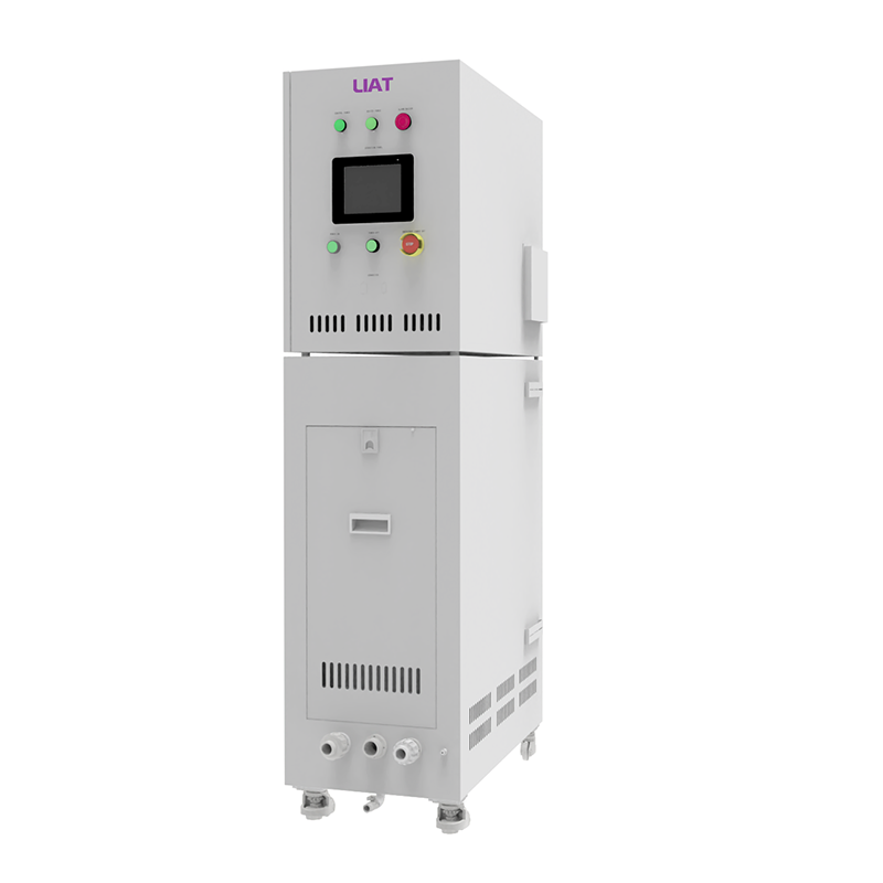
An industrial chiller may provide the cooling side of this process when the program calls for controlled heat removal. Where both heating and cooling are needed, a temperature-control system can switch or blend modes around the prescribed profile. The relevant question is not whether an industrial chiller is large in isolation. It is whether its available cooling, circulation, and control behavior match the pack’s expected load and the test’s transient demands.
Why chamber temperature and coolant temperature are different tests
A thermal chamber controls the air surrounding a pack. That approach is useful for ambient exposure, storage, soak, and enclosure-related evaluations. A battery pack test cooling system, by contrast, directly conditions the liquid in the pack’s thermal circuit. It can therefore examine how the pack responds when coolant temperature, flow, or pressure changes while electrical loading changes too.
These methods can complement each other, but they do not produce interchangeable evidence. A chamber can create a demanding ambient environment while the direct loop holds a separate coolant condition. Conversely, a direct-loop test can impose a coolant transient that would be difficult to reproduce by changing room air alone. Before selecting hardware, the test team should state which boundary condition is meant to drive the event.
Managing steady heat and short thermal transients
At steady state, the control task is to balance the pack’s heat generation with the test loop’s heat transfer. The inlet condition should remain within the program tolerance while the unit absorbs or supplies the required load. In transient operation, the task becomes more demanding. A rapid change in charge current, a programmed inlet-temperature step, or a shift in flow target can produce lag between the test unit, the piping, and the pack itself.
A capable battery pack test cooling system manages this with feedback from temperature and flow sensors, a circulation pump, heating and cooling stages, and control logic that responds to deviation from the target. Still, the measured response includes thermal mass in hoses, manifolds, and the pack itself. For that reason, test plans should document sensor locations, fluid volume, insulation assumptions, and the time allowed for stabilization. Without that context, two similar temperature traces may mean different things.
Inputs that shape the cooling-system configuration
Configuration should begin with the test program. A practical requirements review normally covers:
- Temperature window and ramp profile: inlet setpoints, tolerances, dwell times, and transition rates.
- Heat load profile: steady load, peak load, duration, and whether the system must heat as well as cool.
- Coolant and compatibility: the approved fluid, concentration, cleanliness requirements, and wetted-material compatibility.
- Flow and pressure: required range, allowable pressure drop, pump behavior, and connection geometry.
- Pack interfaces: hose sizes, fittings, electrical isolation needs, communication signals, and test-cell interlocks.
- Safety workflow: leak checks, fault response, ventilation, isolation, and emergency-stop integration appropriate to the lab procedure.
For example, an industrial chiller sized around a nominal load may be adequate for a long soak but unsuitable for a profile with large, short-duration peaks. In that case, the cooling capacity, heater response, fluid reservoir, valve behavior, and control tuning all deserve review together.
Using the test data at pack level
The value of a battery pack test cooling system is the repeatability of the boundary condition it creates. Once inlet temperature, flow, pressure, electrical load, and ambient conditions are logged together, the team can compare pack response across operating states. Useful questions include: Does the pack reach a stable temperature difference? Does a change in flow alter the response? Does the control strategy react as expected during a programmed transition? Are return-temperature changes consistent with the imposed electrical load?
These observations should be reported with their conditions and limits. A result from one coolant, plumbing layout, state of charge, and ambient condition does not automatically transfer to every pack configuration. Where a customer specification or an automotive climatic test procedure applies, the final profile and acceptance logic should be checked against the current approved requirement.
A practical way to plan the test loop
Start by translating the test request into a heat-and-flow profile. Confirm the pack ports, coolant, permitted pressure, expected heat load, temperature range, electrical test states, and data connections. Next, determine whether the work calls for direct coolant control, ambient control, or both. Then validate the battery pack test cooling system under representative loop conditions before relying on it for a full pack program.
That approach keeps the discussion focused on evidence: the system conditions the pack boundary, records how the boundary was held, and makes thermal behavior easier to interpret. With the operating conditions defined upfront, the cooling loop becomes a controlled part of the test method rather than an uncertain variable in the result.
 Hot News