
How a Battery Testing Cooling System Handles Multi-Cell Packs
When a lab moves from a single cell to a module or pack, temperature control stops being a background utility. A battery testing cooling system has to manage heat entering and leaving many connected cells while preserving a test condition that can be measured and repeated. From an operator and maintenance perspective, the useful question is not simply whether the display reaches a setpoint. It is whether the fixture, coolant loop, sensors, and safety controls keep the pack within the test plan as current, state of charge, and heat generation change.
That distinction matters because battery thermal-management work aims to keep cells in an intended temperature range while limiting cell-to-cell variation. A pack can look stable at one air sensor yet contain warmer locations near a busbar, a less-supported cell, or a restrictive coolant path. A well-planned battery testing cooling system makes those differences visible and manageable rather than assuming that one chamber reading represents the whole assembly.
Start with the thermal load, not the cabinet setpoint
Multi-cell packs introduce several heat paths at once. Cells generate heat during charge and discharge; interconnects and contact resistance can add local heating; the fixture may conduct heat from the cells at different rates; and the enclosure exchanges heat with the room. The cooling system must respond to the combined load, including changes over a drive cycle or pulse sequence. Empty-chamber performance is therefore not enough for setup decisions.
A practical commissioning record defines the target temperature range, allowable temperature spread, expected electrical profile, pack mass, fixture materials, coolant type, and ambient conditions. If only the target temperature is known but the heat load is unknown, what is the basis for comparing cooling approaches? That information lets engineers size and tune a battery testing cooling system around the actual experiment rather than a nominal chamber specification.
How the cooling loop distributes temperature across the pack
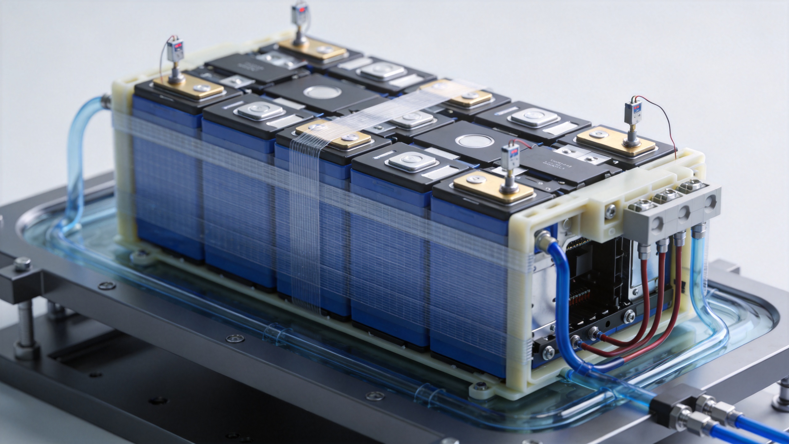
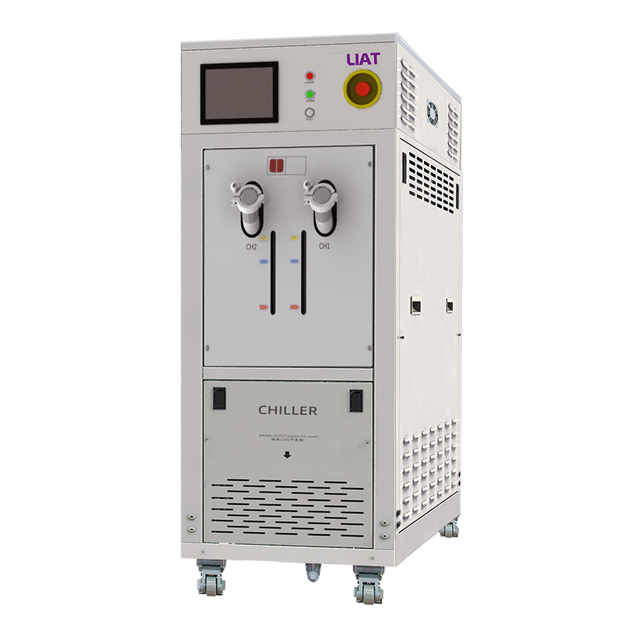
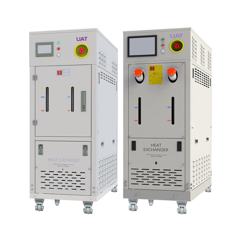
In a liquid-cooled arrangement, a circulating loop commonly includes a reservoir, pump, heat exchanger or refrigeration section, supply and return lines, manifold, cold plate or fixture channels, and temperature/flow instrumentation. An industrial chiller can provide controlled fluid to that loop, but its value depends on the connection boundaries around it. Hose length, elevation, quick-connect restrictions, channel geometry, trapped air, and flow balancing all influence what reaches each area of the pack.
The control objective is not to force every point to the same instantaneous reading. It is to apply the specified boundary condition consistently enough that the measured electrical and thermal response can be interpreted. For a multi-cell pack, this usually means checking supply-versus-return temperature, flow or pressure indicators where available, and representative cell or module temperatures. A battery testing cooling system should also avoid placing a single sensor where it only reports the easiest-to-cool location.
Fixture contact is part of the thermal system
Cold plates, clamps, insulation, and compression features shape the heat path as much as the refrigeration unit does. Uneven contact pressure or a gap beneath one region can create a local lag that looks like a cell difference. Conversely, a highly conductive fixture can mask a characteristic the test plan intended to observe. Before treating a difference as a battery result, verify that the mechanical stack-up, thermal contact materials, and sensor attachment method are consistent with the protocol.
Site conditions deserve the same attention. Installation space, ventilation, and nearby heat sources can affect cooling performance. Checking these conditions during commissioning is more useful than assuming a facility environment is neutral.
Use sensors to verify equilibrium and detect gradients
Setpoint attainment and thermal equilibrium are different events. The controller may report the requested temperature while the pack core, fixture, and coolant return are still converging. A dependable battery testing cooling system therefore uses a stabilization rule in the test method: selected temperatures must remain within the defined band for the defined observation period before the electrical sequence begins.
Sensor placement should reflect the pack architecture and test risk. Typical review points include a cell near the coolant inlet, one near the outlet, a location expected to see higher current-path heating, a more insulated region, coolant supply and return, and the surrounding enclosure. The correct count and locations come from the pack design and protocol, not a generic template. Logging synchronized current, voltage, coolant conditions, and temperatures makes it easier to determine whether a rise followed electrical loading, a flow problem, or a sensor issue.
Coordinate cooling control with the battery cycler and safety layer
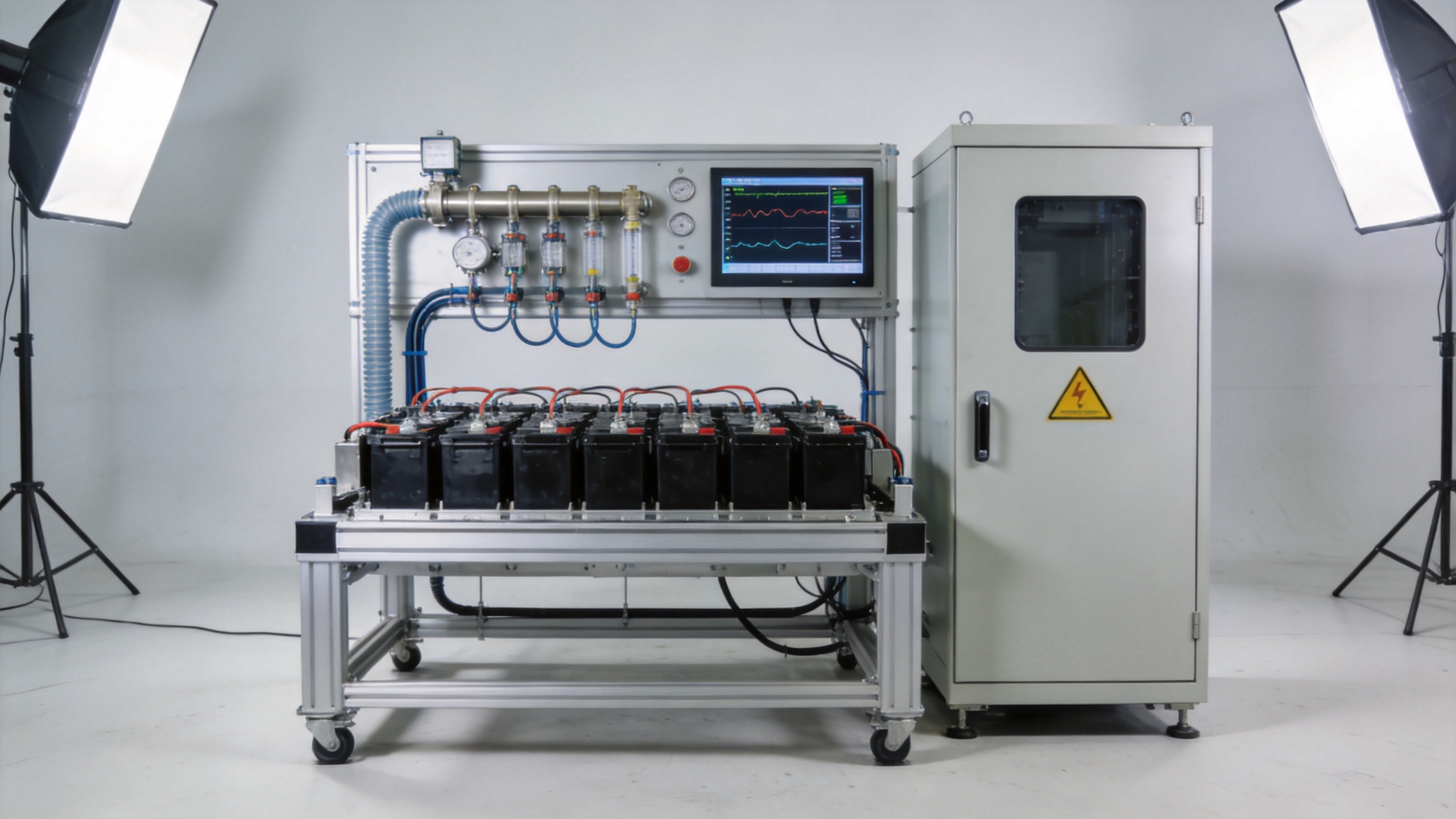
A multi-cell test stand is a coordinated system. The cycler changes electrical load; the pack produces or absorbs heat; the cooling loop responds; and safety logic watches for conditions outside the approved envelope. The battery testing cooling system should exchange only the signals that the validated setup requires, such as run permission, alarm status, and measured conditions. Interlocks, independent temperature limits, leak detection where appropriate, and emergency-stop behavior should be defined before an unattended sequence is allowed.
It is useful to distinguish normal process control from protective action. Process control adjusts cooling capacity or flow to follow the test condition. Protective action responds when a measured value crosses the protocol limit or a sensor/fault status makes the data unreliable. Recording the event, the affected channel, and the system state helps a team decide whether a run is valid, needs review, or must be repeated.
A commissioning sequence for multi-cell pack testing
- Map the test boundary. Confirm the temperature condition, electrical profile, pack configuration, fixture, coolant medium, and required safety limits.
- Inspect the fluid path. Check connections, fill level, air removal procedure, flow direction, and accessible supply/return measurements.
- Verify sensors. Confirm identification, attachment, logging channels, and a placement plan that can reveal pack gradients.
- Run a controlled stabilization check. Allow the fixture and pack to settle under the protocol conditions before applying the full electrical sequence.
- Apply a representative load profile. Review temperature trends with current and coolant data, then investigate persistent differences before treating them as cell behavior.
- Document the configuration. Preserve setpoints, limits, calibration status, coolant information, fixture revision, and any deviations for later comparison.
Common trouble comes from treating the target temperature as the only requirement. A battery testing cooling system may appear to be operating normally while a blocked branch, poor fixture contact, or an undersized flow path leaves part of the pack on a different thermal trajectory. Experience helps identify questions, but final conclusions still need the project records and test data.
Where an industrial chiller fits in the decision
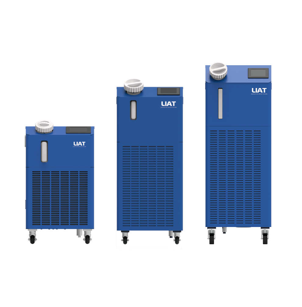
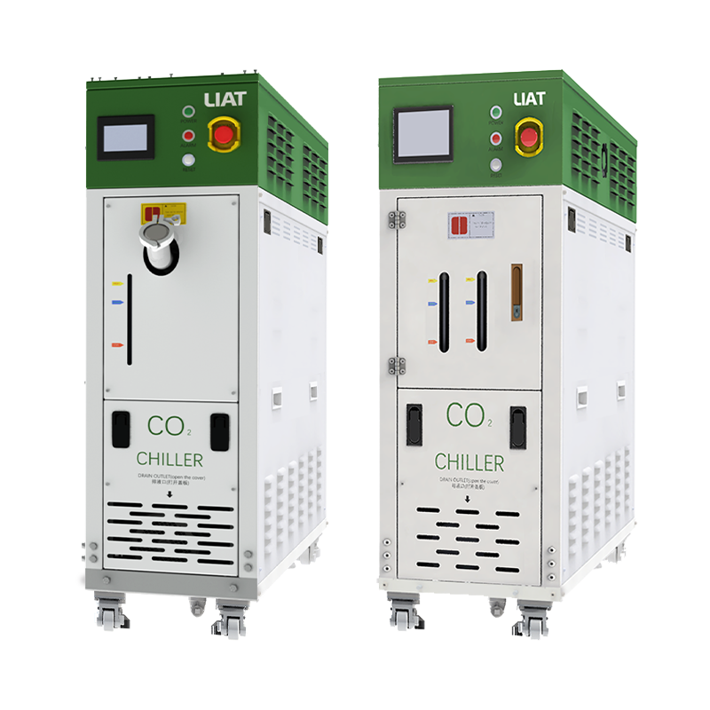
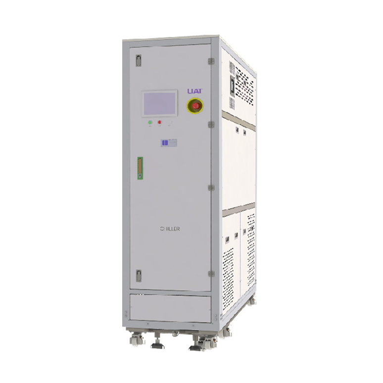
An industrial chiller is one possible source of regulated coolant for pack fixtures or a secondary loop. Selection should be based on the required temperature range, dynamic heat load, coolant compatibility, flow and pressure needs, control integration, installation conditions, and maintenance access. The purchase decision should also include the connection details: piping, electrical supply, controls, and the practical ability to inspect and service the loop during a test campaign.
For teams evaluating a battery testing cooling system, asking for those conditions early creates a clearer engineering discussion than requesting a capacity number alone. It also helps purchasing, engineering, and operators assess the same setup from different angles: fit to the protocol, evidence from commissioning, and maintainability over repeated test cycles.
Conclusion
A multi-cell pack turns temperature control into a measurement-quality issue. The right battery testing cooling system combines a defined thermal boundary, balanced heat removal, representative sensing, coordinated controls, and documented stabilization. By checking gradients and connection details as carefully as the setpoint, a test team can build a more interpretable basis for pack-level results.
 Hot News