
Why a BMS Test Chiller Safeguards Battery Control Validation
In this article, BMS means battery management system, not a building-management system. That distinction matters. A BMS test chiller is used to create repeatable coolant conditions around a battery thermal loop while engineers observe how the controller measures temperature, commands protection, and responds to changing heat load. It does not make a battery safe by itself. It makes the thermal input to a validation exercise more defined, so the team can tell whether a response came from the BMS logic or from an uncontrolled test condition.
From a thermal-management application engineer’s viewpoint, the useful question is not “Can the chiller make the coolant cold?” It is “Can the test setup demonstrate, with traceable measurements, that the battery control strategy behaves as intended across the operating conditions that matter?” An industrial chiller used in this role needs to be considered as part of the fixture, instrumentation, safety plan, and test sequence.
Controlled Temperature Turns a Thermal Test into Control Validation
Battery behavior, sensor readings, cooling demand, charge acceptance, and protective limits can all vary with temperature. If the coolant supplied to a pack is drifting, poorly measured, or changing for reasons the test team cannot explain, an apparent BMS fault may actually be a facility-side problem. A BMS test chiller helps separate those variables by providing a programmed thermal boundary condition to the battery cooling circuit.
That separation is important when validating decisions such as pump requests, fan commands, coolant-valve logic, derating thresholds, diagnostic flags, and fault recovery. The test does not simply ask whether a command appears on a bus. It asks whether the command appears at the right time, under a known thermal condition, and with a response that agrees with independent sensors and the intended requirements.
A BMS test chiller is different from an ambient thermal chamber. A chamber controls the air surrounding a cell, module, or pack. A coolant-conditioning system directly controls the fluid passing through the battery thermal-management loop. Many programs use both, but they answer different questions. Mixing the two without stating which boundary is controlled can make later results difficult to interpret.
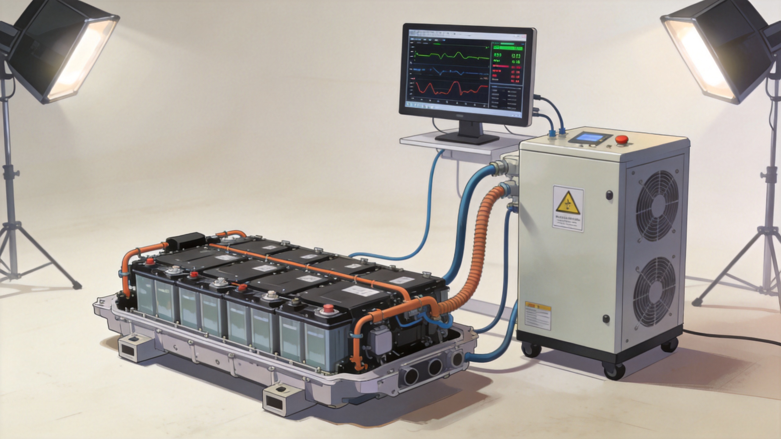
What the Chiller Must Make Observable
Validation becomes more useful when the thermal setup produces measurements that can be compared rather than impressions that someone must interpret afterward. Before selecting or configuring an industrial chiller, define the signals that will be logged at the same sampling basis as the BMS data.
- Coolant supply and return temperature: These show the actual thermal condition delivered to and recovered from the unit under test.
- Flow and pressure, where applicable: Temperature control without sufficient circulation can hide a loop restriction, an air pocket, or a pump-control issue.
- Pack, module, and sensor temperatures: These allow the team to compare BMS-reported values against independent instrumentation.
- BMS commands and states: Log cooling requests, faults, derates, contactor state, and diagnostic timing with synchronized timestamps.
- Electrical load context: Charge/discharge current and voltage change the heat source. They should be recorded with the thermal data, not added later from memory.
This is where a common mistake appears: teams specify a nominal coolant temperature but do not define stability, ramp behavior, sensor placement, or the acceptable difference between the chiller display and the measurement at the pack inlet. The nominal setting is not the same thing as a verified boundary condition.
A Practical BMS Test Chiller Validation Sequence
A repeatable program usually starts by turning the requirement into thermal states and expected control outcomes. Exact temperatures, rates, dwell periods, and protection limits must come from the applicable battery specification, risk assessment, and test procedure. They should not be copied from a generic article.
- Establish the baseline. Stabilize the coolant loop at a documented condition. Confirm that independent inlet and outlet sensors, BMS readings, and data-acquisition timestamps agree within the project’s allowed measurement uncertainty.
- Run controlled transitions. Change coolant conditions at the planned rate and observe when the BMS requests cooling, changes limits, or records a diagnostic. A gradual transition often reveals filtering and hysteresis behavior that a single step cannot show.
- Apply representative heat load. Combine thermal conditioning with the electrical duty that represents the intended use case. This exposes whether control logic remains internally consistent when coolant temperature and internally generated heat move together.
- Challenge sensor plausibility. Where the approved procedure permits it, introduce bounded sensor offsets, disconnected signals, or implausible-rate conditions through a safe test connection. Check whether the BMS identifies the condition and moves to the expected state.
- Verify recovery. Return the loop to a stable condition and document how the BMS clears, latches, or retains its response. Recovery behavior is often as important as trip behavior.
For thermal-abuse or regulatory testing, a separate safety protocol may prescribe specific ramp-and-soak conditions. Those conditions are not default BMS test chiller settings. The test team should use the applicable standard and facility safety controls rather than treating a validation bench as a substitute for a dedicated abuse-test arrangement.
Why Coolant-Loop Details Matter
The chiller, hoses, quick connects, heat exchanger, pump, and fixture can alter what the battery sees. Long or undersized lines add thermal lag and pressure loss. A large reservoir can smooth a transition that the BMS should have experienced more quickly. Poorly located temperature probes can report a condition that is not representative of the pack inlet. None of these findings means the BMS is wrong, but they can create misleading pass/fail evidence.
For that reason, define the test boundary in the procedure: identify the controlled variable, the measurement point used for acceptance, the circulation path, the coolant medium, and any permitted offset between the setpoint and pack inlet. The industrial chiller is then evaluated for its fit to the boundary, not only for its brochure temperature range.
Common Gaps a Test Chiller Can Expose
A well-instrumented BMS test chiller setup can reveal gaps that static software review may not show. Examples include a cooling request that arrives too late after a coolant transition, a sensor filter that masks a fast change, contradictory signals between a pump request and a fault state, or recovery logic that behaves differently after a sustained temperature excursion. These are system-level observations. They need correlation across thermal, electrical, and communication data before any conclusion is assigned to the BMS or the thermal hardware.
It is also useful to distinguish a control-validation result from a battery-performance result. A test may show that the BMS issued a request at the specified threshold, yet the pack temperature may still change slowly because of fixture thermal mass, flow constraints, or the selected duty cycle. Both findings can be valid, but they answer different engineering questions.
Specification Questions Before You Build the Bench
Before committing to a BMS test chiller, align the test owner, battery engineer, controls engineer, and safety lead around a concise input sheet:
- What coolant medium, temperature window, and transition profile are required?
- What heat-rejection or heat-addition duty is expected at each phase of the program?
- Where is the controlled temperature measured, and what uncertainty is acceptable?
- What flow, pressure, hose length, and connector constraints are imposed by the battery fixture?
- Which BMS states and signals define a pass, a warning, or an investigation?
- What interlocks, leak detection, ventilation, isolation, and emergency actions are required by the battery test safety plan?
Answering these questions early prevents an industrial chiller from being treated as a stand-alone purchase. It is a controllable part of a broader validation system.
Conclusion
A BMS test chiller safeguards battery control validation by making the coolant-side condition deliberate, measurable, and repeatable. It helps the team distinguish controller behavior from bench variability, test sensor plausibility under bounded conditions, and document recovery after thermal events. The value comes from the whole method: a defined thermal boundary, synchronized measurements, a safe fault-injection plan, and criteria tied to the actual battery requirement. When those elements are in place, thermal testing produces evidence that is more useful for design decisions and validation records.
 Hot News