
How a CVD Gas Line Heating System Prevents Solid Deposits
In a CVD tool, a precursor can leave its source as a stable vapor and still become a process problem before it reaches the chamber. A cooler fitting, valve body, bend, or uninsulated section can move part of that vapor back toward its condensation limit. Material then collects on the wall instead of arriving at the reaction zone. A properly designed cvd gas line heating system manages that transport path as one temperature-controlled envelope, helping the process keep material in the intended phase while avoiding a temperature that could damage the precursor.
From a semiconductor equipment-integration perspective, the useful question is not simply whether a line is heated. It is whether source conditions, transfer-line temperature, pressure, transport-gas flow, valves, and the chamber inlet work together. CVD depends on control of temperature, pressure, and gas flow; changing one of those conditions can change what happens in the others. That is why a heating design should be reviewed against the actual precursor chemistry and operating sequence rather than treated as a generic accessory.
Why solids form in a precursor delivery line
Many liquid and solid CVD precursors have limited vapor pressure at room temperature. Their delivery therefore starts with controlled source heating or another vapor-generation method. Once vapor enters the transfer path, its ability to remain gaseous depends on the local temperature and pressure. If a surface is colder than the rest of the path, vapor molecules can condense there. Depending on the chemistry and subsequent exposure, that condensed material can leave a film, particles, or a hard deposit.
The first visible symptom may be different from a blocked tube. Operators may see drift in delivery pressure, longer stabilization time, a changing response to a valve pulse, or an unexpected difference between source conditions and chamber-side flow behavior. These signs do not prove a deposit on their own. They do, however, justify checking the thermal map before assuming that a flow controller or source container is at fault.
A cvd gas line heating system addresses this failure chain by limiting temperature discontinuities. It does not make every precursor behave the same way. Instead, it gives the engineering team a controllable condition: each wetted section is kept within the approved delivery window for that chemistry, pressure range, and residence time.
Continuous heating matters more than a high setpoint
It is tempting to solve a condensation concern by raising the heater setpoint. That approach can create a different problem. A source or line temperature high enough to maintain vapor may also accelerate decomposition for a thermally sensitive precursor. Published solid-source delivery designs describe this same balance: heat the source and lines enough to maintain the vapor state, yet avoid significant thermal decomposition. The engineering target is therefore a bounded thermal profile, not the highest available temperature.
In practice, temperature continuity deserves special attention at connections. Tube heaters may cover straight runs well while leaving a gap at a valve, regulator, filter, quick connection, mass-flow device, or chamber inlet. A short unheated metal section can draw heat from the gas stream and become a deposition site. Insulation, heated enclosures, jacket overlap, and sensor placement are all ways to assess that connection, but their suitability must be verified for the materials, electrical classification, and maintenance needs of the tool.

Four locations to map before commissioning
- Source outlet: Confirm that the first wetted fitting does not sit below the delivery condition established at the source.
- Valves and bends: Review larger metal masses and direction changes, where heat loss and residence time can differ from a straight tube.
- Instrument connections: Check any component whose allowable temperature, seal material, or control behavior limits the line setpoint.
- Chamber-side inlet: Evaluate the final transition so the precursor reaches the intended process zone without a cold interruption.
How the heating system supports stable delivery
A cvd gas line heating system usually combines heated transfer sections, temperature sensors, control zones, insulation, and alarms or interlocks. The purpose is to make thermal behavior observable and repeatable. Separate zones can be useful where source, line, and connection conditions have different requirements. Sensor readings should represent the relevant wetted path as closely as the installation allows; a sensor mounted far from the likely cold spot may give a reassuring number while the local surface is still cooler.
Pressure and flow data add context. A line can be at the intended temperature but still operate near a phase boundary if pressure, transport-gas dilution, or source output changes. Conversely, a pressure change can make a marginal cold spot visible. Trend the variables together during warm-up, steady delivery, purge, and shutdown. The transitions are often more revealing than one stable set of readings.
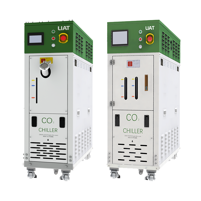
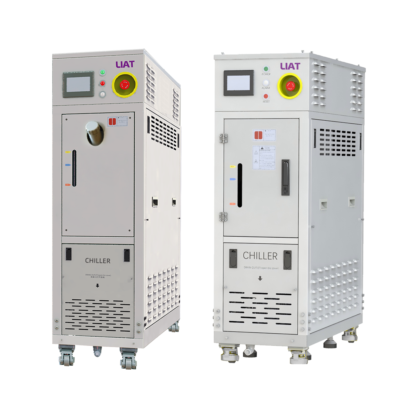
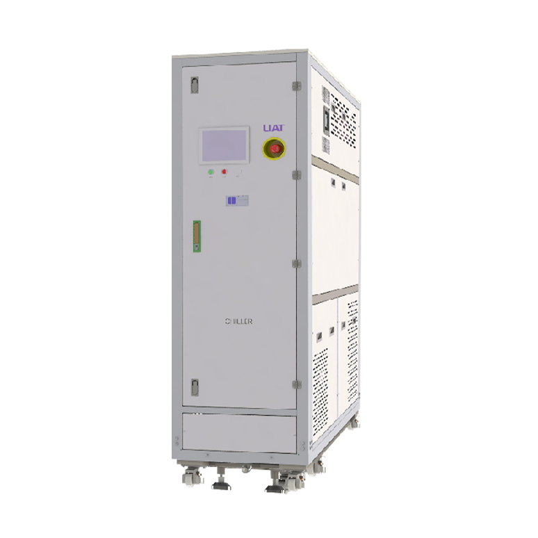
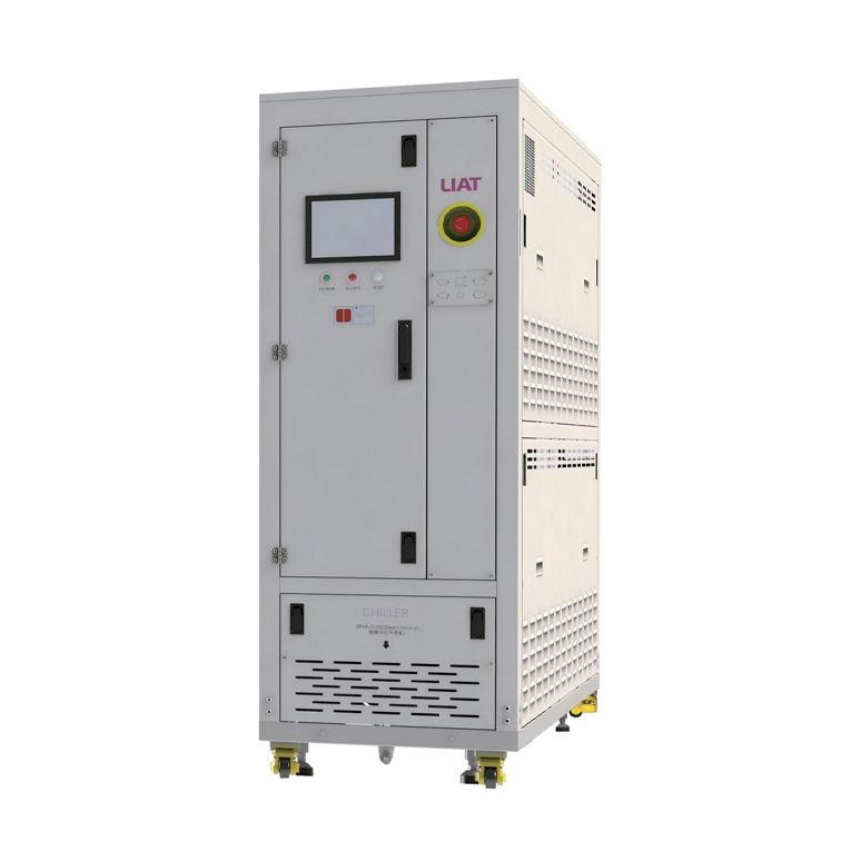
This is also where an industrial water chiller may enter the wider equipment discussion. A chiller that serves chamber hardware, pumps, or other thermal loads should be considered as part of the tool’s overall heat balance, but it should not be treated as a substitute for controlled precursor-line heating. The two systems can have different temperature objectives. Verify physical separation, insulation, routing, and control logic so a cooled adjacent component does not create an unintended cold region in the delivery path.
A practical troubleshooting sequence
When deposits or delivery instability are suspected, begin with documented conditions rather than changing multiple setpoints at once. Record the precursor identity, source condition, line-zone readings, pressure, transport-gas flow, valve timing, and the point in the recipe when the behavior appears. Then compare the actual installation with the thermal design: look for exposed fittings, failed heater segments, compressed insulation, sensor drift, poorly coupled probes, or a recent routing change.
Next, inspect the process sequence. A purge may cool a low-flow leg; a long idle period may leave a valve island outside its normal control band; startup may send material through a path before every zone is ready. Confirming these conditions helps distinguish a thermal transport issue from a source, control, or downstream restriction issue. Any inspection or service must follow the site’s safety procedures and the precursor supplier’s handling requirements.
What to specify during design review
- The precursor’s approved source and transfer temperature window, including decomposition limits where available.
- Line materials, fitting types, total route length, bends, vertical changes, and components that create unheated mass.
- Required temperature uniformity, sensor locations, control-zone logic, alarms, and warm-up permissives.
- Operating pressure, transport-gas conditions, expected residence time, purge behavior, and shutdown sequence.
- Maintenance access and an inspection plan for locations with a higher likelihood of thermal discontinuity.
These questions turn a cvd gas line heating system into an engineering control rather than a component selected in isolation. The final settings should be validated against the specific precursor and tool configuration. With a continuous, measured thermal path and a bounded temperature window, teams can reduce opportunities for vapor to condense and form unwanted solids before the chamber.
Commissioning checks that reveal cold spots
Before a new recipe is released, map source, straight-run, valve, and chamber-inlet temperatures during warm-up and normal flow. A cvd gas line heating system should be evaluated as a route, not as independent heater readings. Record transport-gas conditions, pressure, zone temperatures, and the time required for each zone to stabilize.
| Location | What to verify | Why it matters |
|---|---|---|
| Source outlet | The first fitting is within the approved delivery condition. | A drop at the start can seed wall deposition. |
| Valve or filter housing | Heater coverage, probe location, and component temperature limits agree. | Large metal bodies can behave differently from straight tubing. |
| Idle branch | Temperature recovery is checked after long pauses and purges. | Low-flow sections can cool without an obvious controller alarm. |
| Chamber inlet | The final connection stays within the validated transport range. | The last transition is still part of the precursor path. |
| Nearby cooling route | Physical separation and insulation are reviewed when an industrial water chiller is nearby. | Adjacent cooling hardware can influence an exposed delivery component. |
For routine maintenance, compare trend data before and after changes to tubing, valves, insulation, or recipes. A cvd gas line heating system that previously ran steadily can develop a local temperature mismatch after service work, even when the controller display appears normal.
Using the temperature map in operations
During qualification, use the cvd gas line heating system map as a baseline for later comparisons. The cvd gas line heating system data should show source temperature, each heated zone, and critical hardware such as valves and the chamber-side connection. When a delivery change appears, compare that record before changing several setpoints at once.
For a process with sensitive vapor transport, the cvd gas line heating system start sequence should release precursor only after the approved zones have stabilized. The cvd gas line heating system shutdown sequence may also need a defined clearing period, based on the chemistry and site procedure. These controls help the team identify whether a change is thermal, flow-related, or connected to another part of the tool.
Finally, keep temperature decisions chemistry-specific. The cvd gas line heating system is most useful when its setpoints, alarms, routing, and service records are reviewed against the actual precursor delivery window. That approach supports a measured transport path rather than relying on a single nominal temperature.
 Hot News