
What CVD Gas Delivery Heating Demands from a Heating Jacket
CVD gas delivery heating is often treated as a simple setpoint problem: wrap the line, select a controller, and hold a temperature. In practice, the heating jacket is only one part of a thermal path that includes the source vessel, tubing, valves, fittings, insulation, ambient exposure, sensors, and the receiving process. A nominal setpoint can be useful, but it does not by itself establish the temperature seen by the flowing material.
From a semiconductor equipment integration perspective, CVD gas delivery heating should begin with the chemistry and the physical route, not a generic heater rating. Heated flow lines are commonly used to reduce condensation in vapor delivery paths. The required temperature, however, depends on the material, pressure, flow behavior, line construction, and operating sequence. Those inputs should be confirmed through the process owner’s approved data and safety review.
Start with the thermal duty, not the jacket label
For CVD gas delivery heating, the relevant duty is the heat lost from the installed assembly and the heat needed during startup or changing conditions. A short, well-insulated straight section behaves differently from a long route with bends, valve blocks, supports, and exposed metal fittings. Each discontinuity can become a cooler location or a place where the sensor no longer represents the critical surface.
That makes a heating-jacket request more than a line-diameter and length exercise. Start with the tube material and wall thickness, then capture fitting geometry, the desired operating window, ambient conditions, insulation arrangement, route layout, allowable control zones, and expected ramp or recovery needs. If the route changes after design release, the original CVD gas delivery heating assessment may also need review.
Temperature uniformity matters along the entire route
A jacket can show stable controller feedback while another part of the assembly runs cooler. This is especially relevant where bare fittings, clamps, valves, and transition sections interrupt coverage. For CVD gas delivery heating, ask where temperature must be maintained, where it is measured, and what evidence will verify conditions at the points that matter.
Published examples of multi-zone CVD equipment describe independent zones and their own stated uniformity conditions. Those examples should not be read as jacket specifications. They do illustrate an important engineering point: a single setpoint and a temperature-uniformity result are different claims. One line-characterization apparatus reported estimated accuracy of plus or minus 2.2 degrees Celsius at 250 degrees Celsius under its stated test conditions. That figure is not transferable to another installation; it is a reminder to define location, instrument, load, and test condition before comparing results.
For a long or geometrically varied route, divide the discussion into thermal zones when the process and installed layout justify it. Zones may be useful near the source outlet, through a valve manifold, around a vulnerable fitting group, or near the chamber connection. The number of zones should follow the thermal map and controls architecture, not a preference for additional hardware.
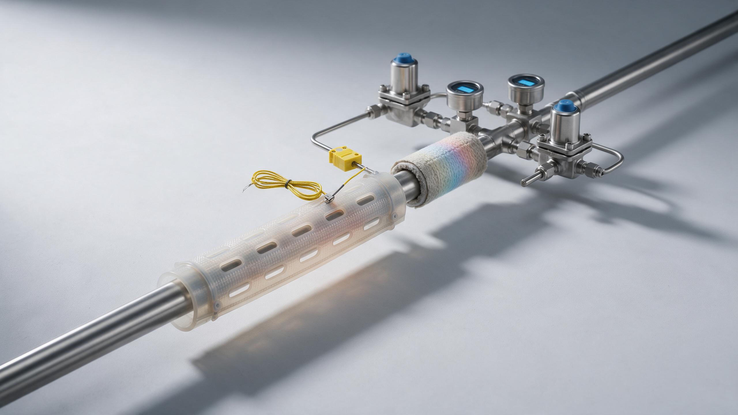
Choose control and sensing as a pair
Reliable CVD gas delivery heating requires a controller, sensor placement, and heater layout that work together. A sensor located beneath a well-covered section may respond differently from an exposed elbow or a large valve body. Conversely, placing a sensor at every visible component may add complexity without improving a validated control strategy.
- Identify the controlled variable: jacket surface, tubing surface, or another approved proxy for process needs.
- Specify where each sensor is attached and how attachment, insulation, and cable routing affect the reading.
- Define high-temperature limits, fault response, alarm handling, and restart behavior with the equipment safety team.
- Confirm whether the process sequence changes flow, pressure, or surrounding heat loads enough to challenge the selected control approach.
This is also where CVD gas delivery heating crosses into machine integration. The heating circuit may need coordinated permissives, status signals, and fault handling with the gas cabinet, process tool, and facility controls. Compatibility and hazardous-area requirements must be verified for the specific installation rather than assumed from a general heating-jacket description.
Mechanical fit affects thermal results and service work
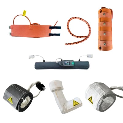
In CVD gas delivery heating, the jacket needs repeatable contact across the line while allowing access to fittings, labels, inspection points, and maintenance tasks. A loose wrap, a compressed insulation layer, a shifted closure, or a recurring removal cycle can change the installed heat-transfer behavior. The mechanical plan should therefore cover bend radii, branch connections, fastening access, cable strain relief, and the sequence for removing and refitting the jacket.
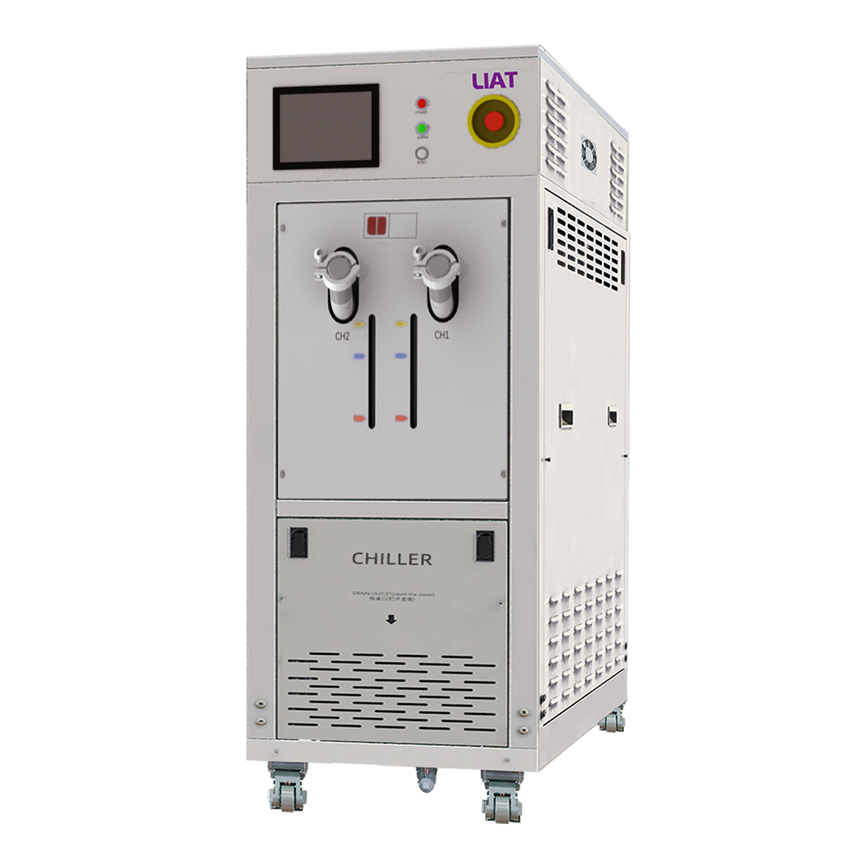
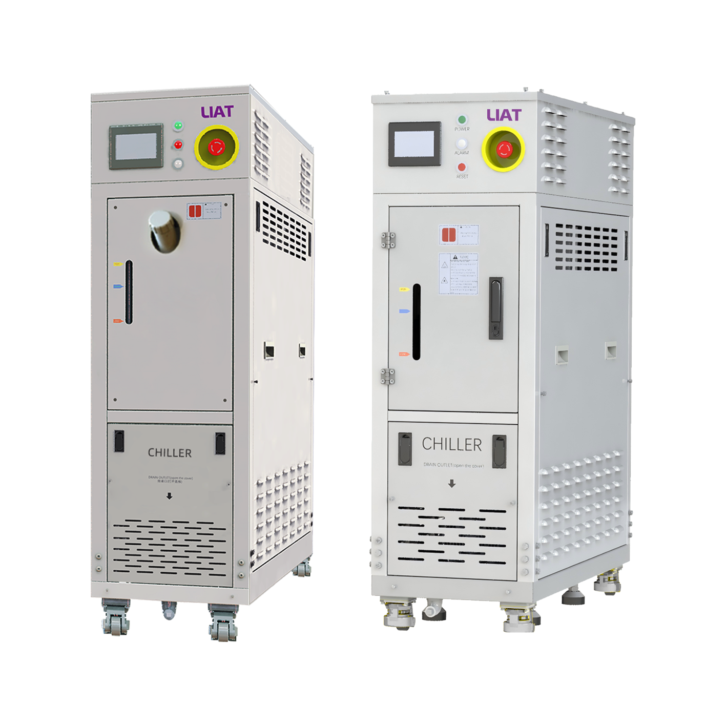
An industrial water chiller may be part of the wider thermal-management environment, but it does not define the gas-line heating requirement. Heating and cooling equipment should be evaluated by their own duty, interfaces, controls, and validated operating boundaries. Treating them as a single substitute calculation can hide the conditions that matter to each subsystem.
Build commissioning around evidence
Before releasing CVD gas delivery heating for process use, create a commissioning plan that states what will be measured and under which operating conditions. Record the route drawing, zones, sensor positions, controller settings, insulation condition, and acceptance criteria approved for the process. Then evaluate steady operation and the transitions that are meaningful for that tool, such as startup, idle periods, flow changes, or maintenance recovery.
The goal is not to claim that every section has the same temperature. It is to show that the installed CVD gas delivery heating arrangement meets the defined process need within an agreed verification method. If an unexpected cool location appears, use the evidence to check coverage, insulation continuity, local heat loss, sensor representativeness, and controls response before choosing a modification.
A practical heating-jacket specification checklist
A clear specification gives suppliers and integrators a common basis for discussion. For CVD gas delivery heating, include the following:
- Material identity and approved operating temperature window from the process owner.
- Line drawings with tube sizes, fittings, valves, branches, and unheated transition points.
- Installed ambient conditions, insulation concept, and physical-access constraints.
- Required zones, sensor locations, controller interfaces, alarms, limits, and interlocks.
- Electrical, materials, cleanability, and site-safety requirements to be confirmed for the actual installation.
- Commissioning measurements, documentation, and acceptance criteria.
For CVD gas delivery heating, treat the jacket as one thermal-control component in a larger assembly, rather than an isolated sleeve with a temperature number. Clear process conditions, route details, control expectations, and a verification plan give the engineering discussion a firmer basis.
 Hot News