
How to Select Battery Test Cooling Equipment for Your Lab
Selecting battery test cooling equipment is less about choosing a large refrigeration number and more about matching a thermal-control system to a defined test. A cell cycling bench, a module fixture, and a pack-level coolant loop put very different demands on the lab. Before requesting quotations, turn the test method into a temperature, heat-load, flow connection, and safety specification.
From a lab thermal-management perspective, the useful question is: what must the equipment control? A temperature chamber manages the air around the specimen. An industrial chiller or liquid temperature-control unit manages the fluid moving through a battery cold plate or thermal circuit. Some programs need both, but they should not be sized as though they perform the same job.
Start with the test architecture
Map the energy path before selecting battery test cooling equipment. In a chamber-based test, heat enters or leaves through the surrounding air, fixtures, cables, and the unit under test. In a liquid-loop test, the control unit exchanges heat with the circulating coolant and must work with the battery’s pressure drop, hose volume, and flow requirement. A direct cooling test may need a different architecture again, particularly if it is intended to represent a vehicle thermal system.
Write down the specimen level and test purpose:
- Cell testing: compact fixtures, low thermal mass, and close sensor placement may matter more than high liquid flow.
- Module testing: look at fixture conduction, parallel paths, and the heat released during the planned charge/discharge profile.
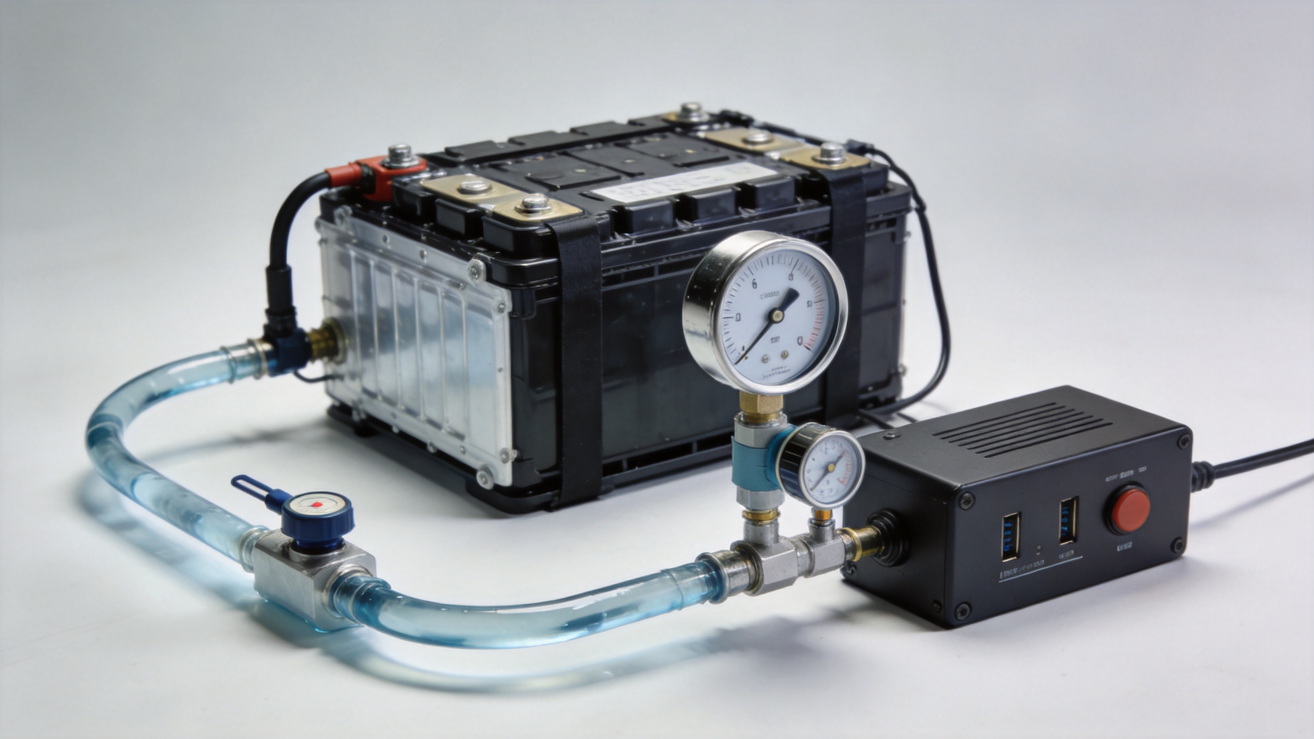
- Pack or coolant-plate testing: define coolant ports, permitted pressure, required flow, loop volume, and whether the equipment must follow a changing setpoint.
- Environmental exposure: decide whether air temperature, humidity, or thermal cycling belongs in a chamber rather than the liquid loop.
Published battery test descriptions commonly cite conditions such as -20°C, 0°C, 25°C, and 45°C for cell characterization. Treat those values as an example of why the required operating envelope must be stated at the beginning; the governing test method and the specimen design set the actual requirement.
Calculate the cooling duty from the test, not the battery nameplate
Cooling capacity for battery test cooling equipment should cover the largest credible heat rejection during the programmed profile, not merely the battery’s energy capacity. Start with electrical losses in the specimen, then add heat from the fixture, pumps, hoses, ambient leakage, and any equipment installed inside a chamber. Fast cycling, high current, repeated charge/discharge steps, and multiple specimens can raise the peak duty substantially above a steady-state estimate.
Ask the test engineer for three cases: normal operation, the highest planned continuous load, and the short-duration peak. Specify the acceptable temperature deviation at the battery inlet and outlet for each case. This gives the supplier a basis for selecting a compressor capacity, heat exchanger, reservoir, and control response without relying on an unqualified safety margin.
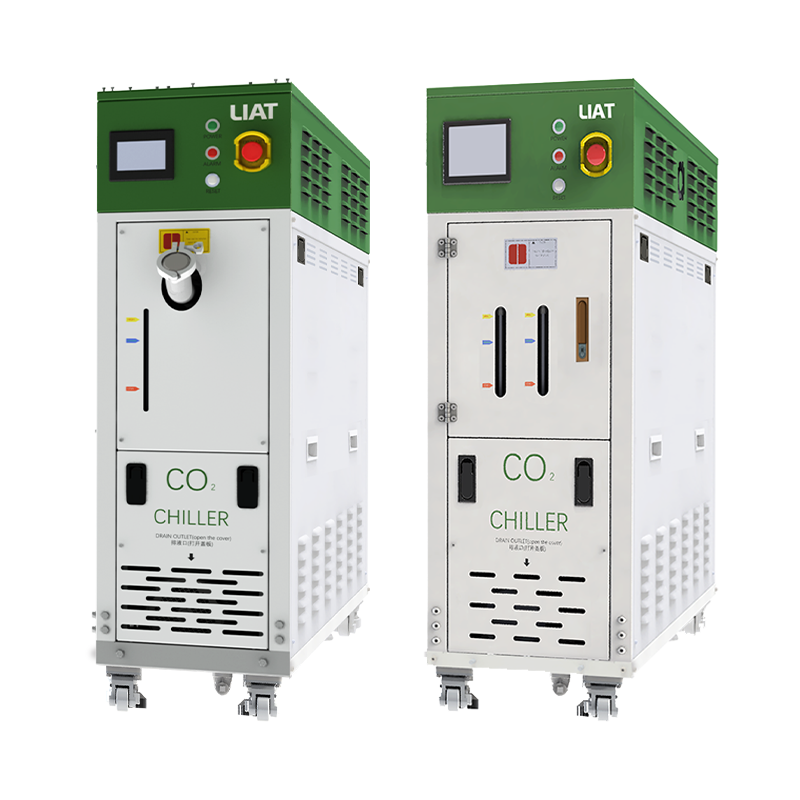
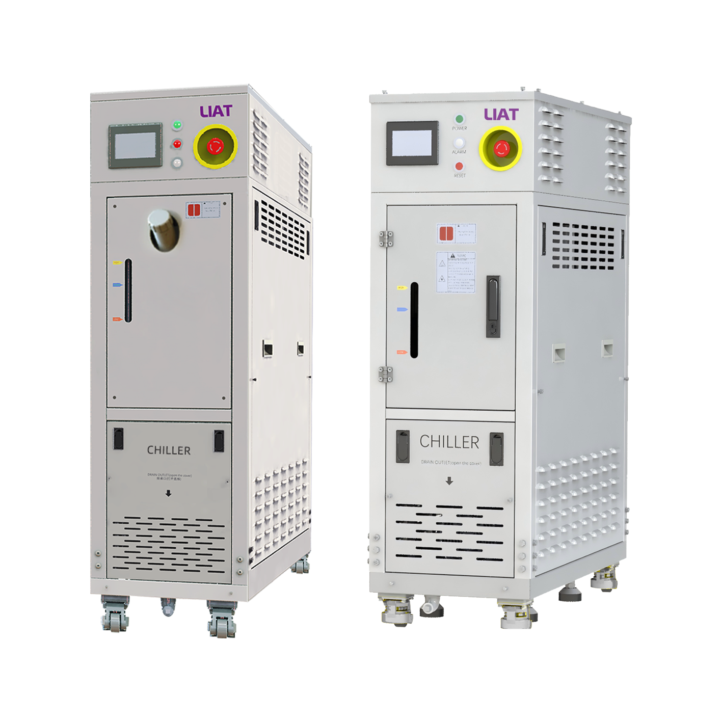
Also distinguish cooling capacity at the required supply temperature from a catalog value measured under another condition. An industrial chiller that is adequate near room temperature may have different available duty at a lower setpoint or with a warmer heat-rejection environment. Document the ambient condition and the heat-rejection arrangement for the installation.
Match temperature range, stability, and ramp behavior
For battery test cooling equipment, the setpoint range answers only one part of the selection. Determine the required stability, sensor location, response to load steps, and rate of temperature change. A lab may only need a stable circulating supply temperature for endurance cycling, while thermal characterization may require controlled transitions and traceable readings at several points on the specimen.
Define whether the control target is supply fluid, return fluid, fixture temperature, chamber air, or a battery surface sensor. These choices affect how the control loop should be configured. If a test script changes current quickly, verify how the system behaves when the thermal load reverses or falls abruptly. A useful factory or site acceptance test reproduces representative setpoint changes and electrical profiles rather than checking an unloaded display.
Confirm coolant circuit compatibility
An industrial chiller must fit the test loop as a hydraulic system. Capture the coolant type, concentration, cleanliness expectation, total loop volume, required flow range, and allowable pressure drop. Check hose and fitting sizes, pump head, filtration needs, and materials compatibility with the selected fluid. If glycol-water mixtures or other approved media are used, their viscosity and heat-transfer behavior should be considered at the lowest operating temperature.
Do not assume that a higher-flow pump is automatically helpful. Excess flow can exceed a fixture or cold plate limit, while insufficient pump head can leave the intended flow unmet once hoses, quick connectors, valves, and the battery circuit are assembled. A flow meter, inlet/outlet temperature measurements, and pressure monitoring make commissioning evidence more useful than a nominal pump specification alone.
Build safety and controls into the purchase specification
Battery tests can involve high current, energized hardware, and abnormal thermal events. Coordinate battery test cooling equipment with the lab’s safety plan, enclosure, ventilation, emergency-stop logic, leak detection approach, and electrical isolation rules. The cooling controller should have clearly defined alarm behavior for overtemperature, low flow, low level, overpressure, communication loss, and sensor faults.
For automated cycling, list the integration requirements before purchase: available communications protocol, commands and readbacks, data timestamps, remote start permissions, alarm contacts, and what state the unit enters after an interlock opens. Define who owns the test-system logic. The cooling system should report its actual condition to the test controller, but it should not be presumed to replace the lab’s independent protection layers.
Use a practical comparison checklist
When comparing battery test cooling equipment, give each supplier the same brief:
- Test object, quantity, and charge/discharge profile.
- Required temperature range, control point, stability, and ramp expectation.
- Calculated continuous and peak heat load at stated ambient conditions.
- Coolant, flow, pressure drop, loop volume, ports, and permitted materials.
- Installation limits: footprint, power supply, water or air heat rejection, drainage, and noise constraints.
- Required controls, data signals, alarms, interlocks, and acceptance-test scenarios.
- Maintenance access, calibration needs, spare parts, and service response expectations.
A comparison is meaningful only when every offer is evaluated at the same test conditions. If one proposal is based on chamber air control and another on direct coolant control, separate the functions before comparing capacity or price.
Plan commissioning before the equipment arrives
Reserve time to commission the entire rig. Verify flow direction, purge air from the loop, inspect for leaks at temperature, confirm sensor naming, and compare controller readings with the lab’s reference instruments. Then run a conservative electrical profile before the full test. Record supply and return temperatures, flow, pressure, ambient conditions, and alarm behavior. Those records provide a starting point for troubleshooting later changes in the battery fixture or test recipe.
The right battery test cooling equipment is the system that meets a written test envelope and integrates cleanly with the lab’s measurement and safety workflow. By separating ambient control from liquid-loop control, calculating duty from the real profile, and validating integration requirements early, a lab can make a more defensible selection of an industrial chiller or other thermal-control solution.
 Hot News