
How a CVD Pipe Heating System Keeps Precursors Vaporized
In a chemical vapor deposition tool, getting a precursor into the chamber is not simply a matter of opening a valve. A precursor that leaves its source as vapor has to remain in a usable vapor phase while it moves through fittings, bends, valves, and the final delivery section. This is the practical role of a cvd pipe heating system: it limits cold spots that can lower the line-wall temperature enough for material to condense, adsorb, or react before it reaches the intended process zone.
From an equipment-integration perspective, the cvd pipe heating system is part of a chain that includes the source, transport-gas or pressure-control hardware, line insulation, chamber inlet, controls, and safety interlocks. The appropriate temperature profile depends on the specific precursor, pressure, flow regime, materials of construction, and supplier handling guidance. For that reason, a setpoint by itself is not a substitute for a verified transport condition.
Why precursor vapor can become unstable in transit
Many CVD and ALD precursors are low-vapor-pressure liquids or solids. They can be delivered as gas-phase material only when the source and line conditions support sufficient vapor pressure and avoid excessive heat loss. If a vapor encounters a cooler surface, its local saturation limit can change. Material may then condense on the wall, remain there as a film, or later re-evaporate unpredictably. The process may see a delayed dose, a drifting concentration, or particles carried downstream.
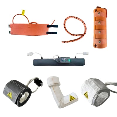
A properly qualified cvd pipe heating system addresses the transport section rather than the chamber reaction itself. It uses controlled heat tracing or a heated assembly, insulation, sensing, and control logic to keep the cvd pipe heating system delivery path within the qualified temperature window. The aim is not unlimited heating of every component. It is to create a stable, documented profile that avoids a colder restriction between the vapor source and the inlet.
The temperature profile matters more than a single reading
A temperature sensor near the source of a cvd pipe heating system does not prove that the entire line is warm enough. Heat can be lost at long unsupported spans, connectors, valve bodies, tees, mass-flow components, and uninsulated transition zones. A line may have an acceptable controller display while a fitting downstream is substantially cooler. For this reason, cvd pipe heating system engineering reviews usually map the whole path and identify its likely thermal weak points.
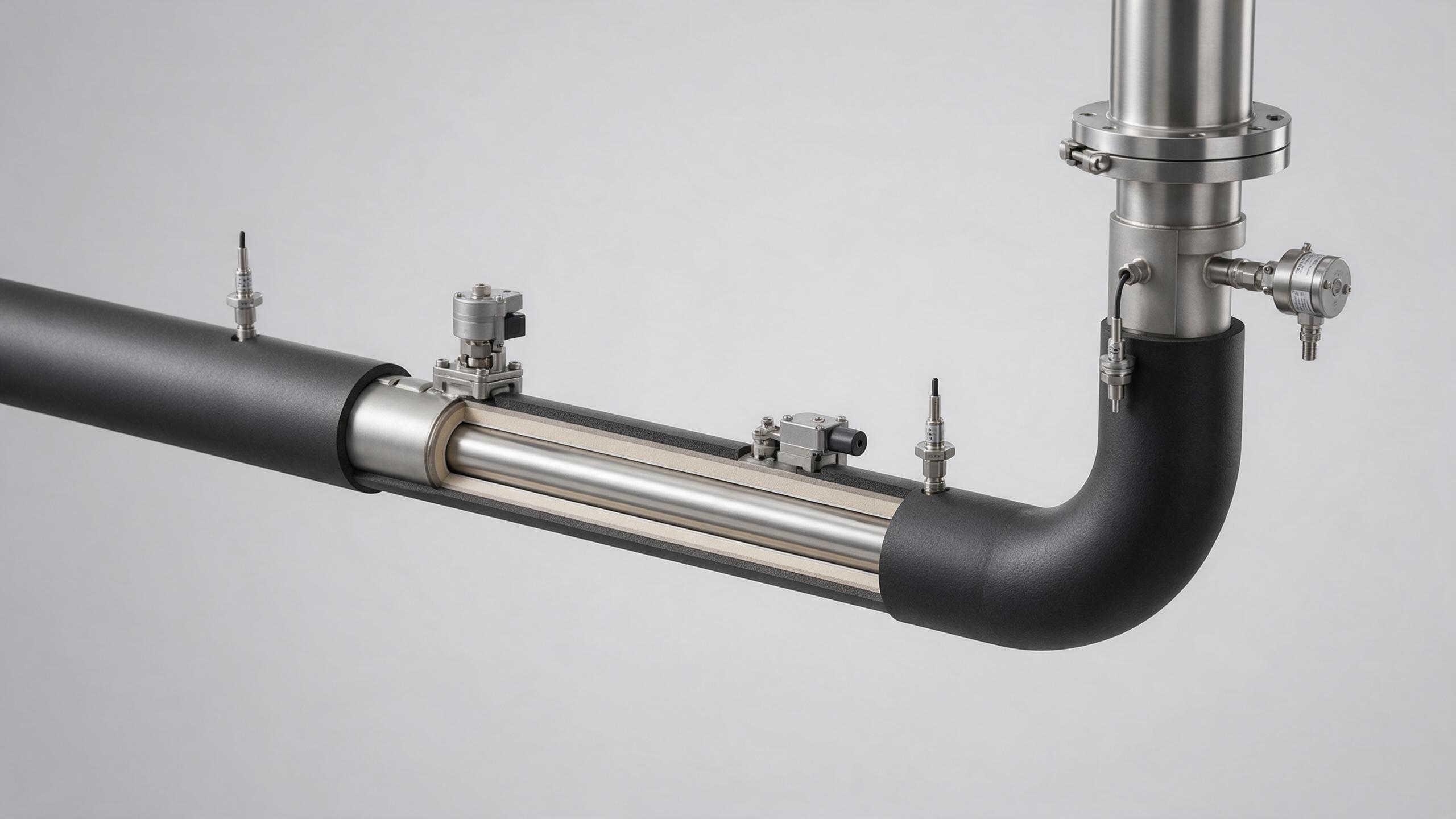
What the heated path typically includes
- Source outlet: The cvd pipe heating system transition out of the bubbler, vaporizer, or source container should be considered with the source-temperature requirement, not in isolation.
- Transfer tubing and bends: CVD pipe heating system routing, bend density, tube material, and insulation affect how readily heat is lost.
- Valves and fittings: CVD pipe heating system valve and fitting mass and exposed surfaces can become local cold points if heat tracing and insulation stop too early.
- Final inlet section: The final cvd pipe heating system segment requires the same attention because a stable upstream line cannot compensate for condensation immediately before the chamber.
- Sensors and controls: CVD pipe heating system sensor placement should represent the components most likely to cool, while alarms should be tied to the qualified operating envelope.
More accurately, a cvd pipe heating system design should be judged against confirmed chemical and connection conditions. The proper line temperature is not a universal CVD setting; it must be compatible with precursor stability, system pressure, seal ratings, valve specifications, and the process owner’s approved recipe.
How a CVD pipe heating system supports consistent delivery
First, the cvd pipe heating system supplies heat along the route so that local wall temperatures do not fall below the transport requirement. Second, cvd pipe heating system insulation reduces the heat loss that the heaters must overcome. Third, cvd pipe heating system sensors and controllers turn heating from a passive installation into a monitored condition. A controller can hold a zone near its target, but commissioning should still confirm whether the actual line geometry produces a uniform result at representative operating conditions.
This distinction matters when heated precursor delivery system flow changes. A low-flow condition may spend more time exchanging heat with the wall; a higher-flow condition can reveal a different temperature or pressure response. Changes in transport gas, source fill level, ambient airflow, maintenance access, or routing can also alter the thermal balance. Instead of treating a heated precursor delivery system as as an isolated accessory, it is more useful to review it as a transport subsystem with process and utility connections.
Do not confuse line heating with an industrial water chiller
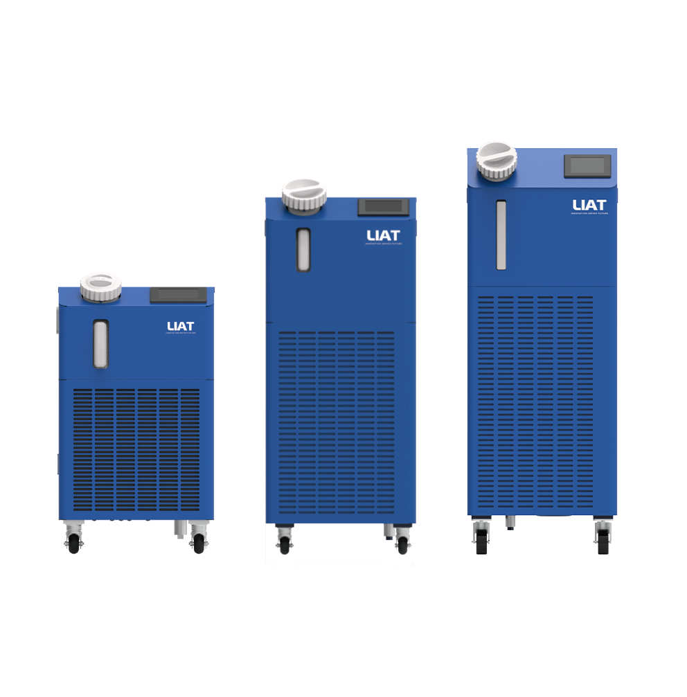
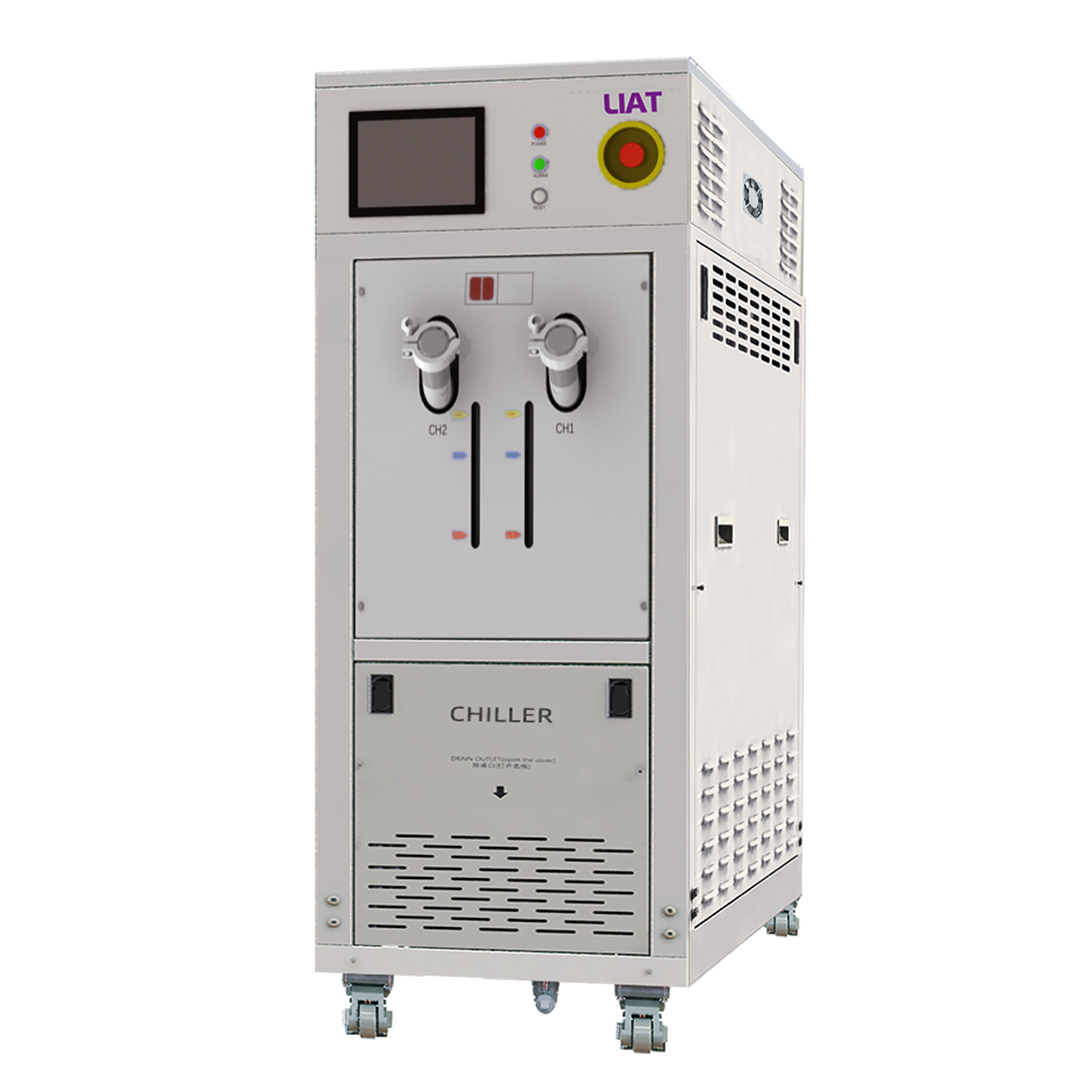
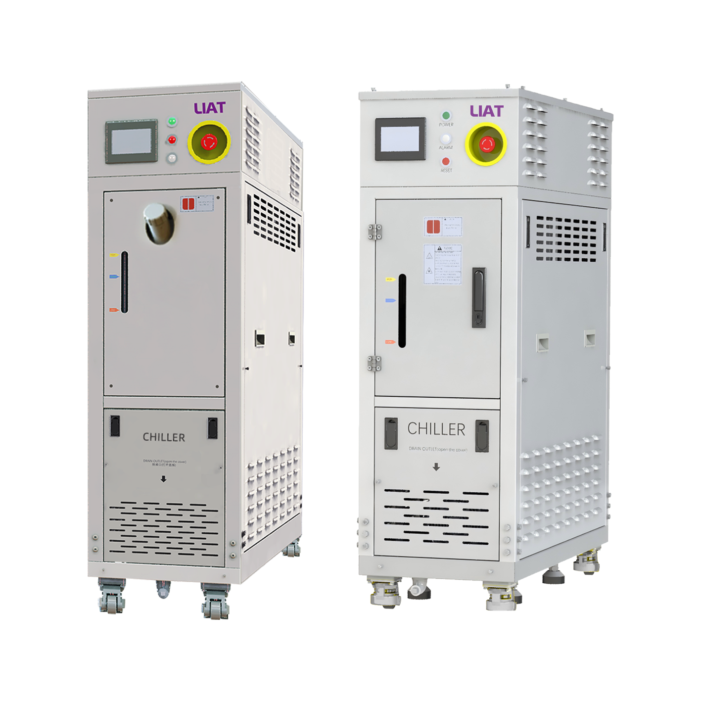
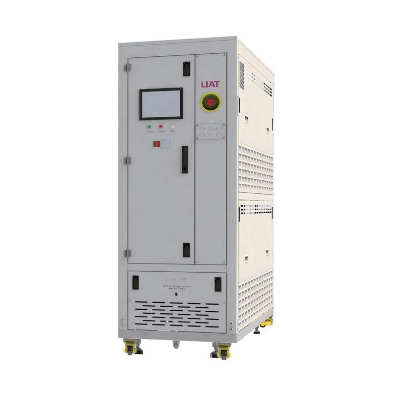
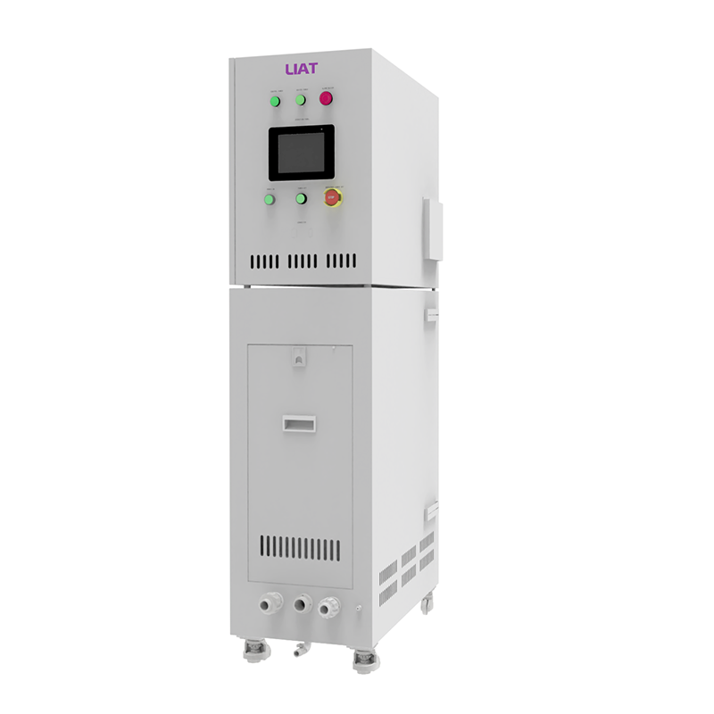
An industrial water chiller may serve a separate thermal-management role in a semiconductor tool or auxiliary equipment, such as removing heat from a condenser, cabinet, power component, or other cooling loop. It does not replace heated precursor delivery system controlled heating required in a precursor delivery path. Heating and cooling can coexist in the same equipment package, but they should be separated by function, tubing route, setpoint logic, and validation plan.
During integration, teams should confirm which circuits carry precursor vapor, which contain process fluids, and which belong to a cooling utility. Clear labels and connection drawings reduce the chance that a cooling line is routed near or mechanically coupled to a heat-sensitive precursor segment without an appropriate thermal barrier.
A practical validation checklist
Before using a heated precursor delivery system in production, teams can convert broad thermal requirements into a short verification plan:
- Obtain the approved handling range and compatibility information for the actual precursor from its qualified documentation.
- Trace the full heated precursor delivery system delivery route from source to chamber inlet, including valves, unions, pressure devices, and serviceable joints.
- Define heated precursor delivery system heating zones and sensor locations around probable heat-loss points rather than only at convenient straight sections.
- Check heated precursor delivery system heater, insulation, tubing, seals, electrical protection, and control hardware against the intended temperature and chemical environment.
- Record heated precursor delivery system warm-up behavior and steady-state temperatures under representative pressure and flow conditions.
- Trend flow and pressure signals during validation. Published work on gas-phase precursor delivery uses flow control and pressure monitoring because these signals help reveal transport behavior that a temperature display alone may miss.
- Document heated precursor delivery system alarm responses, maintenance steps, and requalification triggers after a line is opened, rerouted, or modified.
If a heated precursor delivery system delivery issue appears, avoid assuming that the heater is the only cause. Check the source condition, actual pressure, flow restriction, sensor contact, insulation continuity, ambient cooling, valve configuration, and chamber connection. One observation is rarely enough to identify the root cause; a short time-aligned record of temperature, pressure, and flow is more informative.
What to specify when discussing a heated delivery line
A useful heated precursor delivery system supplier or engineering discussion starts with the precursor’s qualified handling requirements and then covers line length, tube diameter, routing, number of fittings, operating pressure, expected flow range, available power, control-zone needs, insulation, and alarm integration. It is also worth confirming the service sequence: whether technicians can access fittings without damaging insulation or leaving an unheated section after maintenance.
The central heated precursor delivery system question is not whether a line has heaters. It is whether the assembled heated precursor delivery system maintains the required transport conditions from source outlet to chamber inlet under the actual operating envelope. Framing the review this way keeps the discussion tied to process evidence rather than an assumed universal setpoint.
Key takeaway
A heated precursor delivery system helps preserve a controlled vapor path by reducing temperature drops that can lead to condensation or unstable delivery. A sound design connects heat tracing, insulation, sensing, controls, routing, and validation data. For each project, confirm the precursor documentation and system connections first, then qualify the complete delivery path under representative conditions.
 Hot News