
How a Pipe Heating System Handles High Temperature Gas Delivery
Moving a hot gas from one process point to another is not simply a matter of selecting a hotter source. Once gas enters a line, the pipe wall, fittings, valves, supports, and surrounding air continually draw energy away. A well-designed pipe heating system manages that heat loss so the gas reaches the next stage within an agreed operating window. For process engineers, the useful question is not “how hot can the heater get?” but “what temperature must the gas maintain at the delivery point under the real flow, ambient, and control conditions?”
A pipe heating system usually combines a heat source, a thermally conductive path to the pipe, insulation, temperature sensing, power control, and protective devices. Depending on the duty, the heat source may be electrical tracing, a fitted pipe heating jacket, or a purpose-built industrial heating jacket around a component that affects the line. The correct arrangement depends on the gas composition, required delivery temperature, pipe geometry, flow changes, and hazardous-area requirements.
Start With the Thermal Problem, Not the Heater Rating
High-temperature gas delivery becomes unstable when the heat leaving the pipe exceeds the heat supplied to it. That balance changes with ambient temperature, wind or ventilation, insulation condition, line length, pipe diameter, fittings, and gas flow. A pipe heating system therefore begins with a heat-loss calculation and a clear definition of the required temperature at the critical downstream point. A heater selected only from its nominal wattage can be mismatched even if it warms the pipe during a brief test.
The design team should distinguish between heat-up duty and maintenance duty. Heat-up duty is the energy needed to bring a cold line, its fittings, and its contents to operating condition. Maintenance duty is the ongoing energy needed to offset losses once delivery is stable. A pipe heating system sized for maintenance alone may take too long to recover after shutdown; one sized only for rapid heat-up may cycle aggressively unless the controls and sensor placement are considered at the same time.
How Heat Reaches the Gas
In most installations, the heater does not heat the gas uniformly by direct contact. It heats the outside of the pipe, energy conducts through the wall, and the flowing gas receives heat from the inner surface. The effectiveness of a pipe heating system depends on close, repeatable contact between the heater and pipe, adequate coverage at heat-loss points, and insulation that reduces energy escaping outward. Poor contact, gaps beneath insulation, or an unheated valve body can create colder zones even when the controller reports the target temperature nearby.
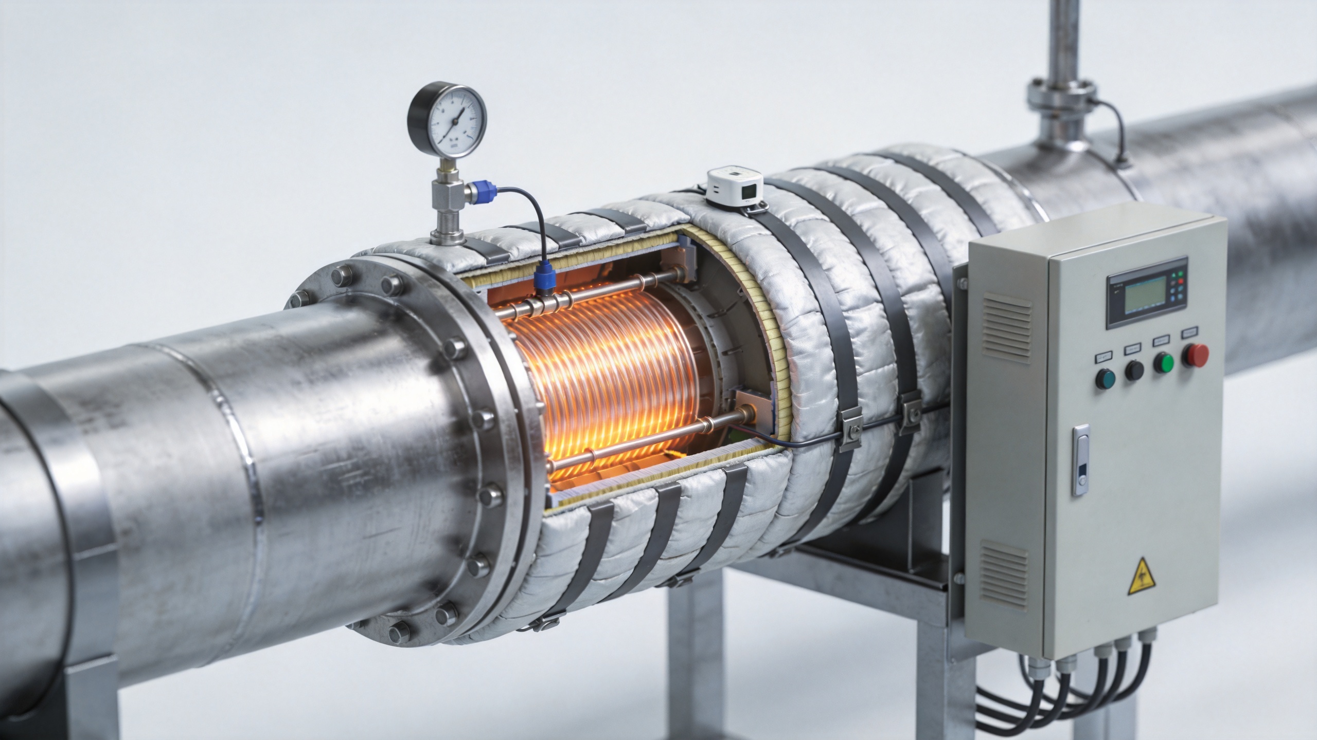
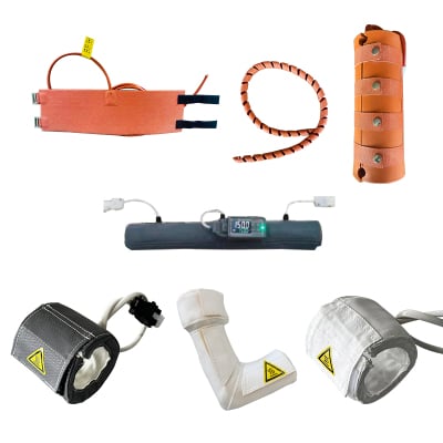
Electric trace systems are commonly used for process-temperature maintenance. The cable is secured along the pipe, then protected by insulation and outer jacketing to reduce heat loss. A pipe heating jacket can be more practical where a removable, shaped enclosure is needed around a short section, elbow, valve, filter, or instrument. An industrial heating jacket may also be used around connected equipment whose thermal condition affects gas delivery. These approaches are not interchangeable by name alone: geometry, service access, surface temperature limits, and control zones should drive the choice.
Why Insulation and Zoning Matter
Insulation is part of the pipe heating system, not an optional finishing layer. It reduces the heater load, improves temperature uniformity, and helps the controller work with smaller swings. However, insulation must be selected for the actual exposure temperature and installed so that water ingress, compression, and gaps do not undermine its thermal performance. Removable sections need the same attention around flanges, sensors, and valves, where losses are often concentrated.
Long or branched lines rarely behave as one thermal zone. A practical pipe heating system divides the line into zones based on pipe size, exposure, process priority, and likely loss locations. The final run to a delivery point may need different attention from an insulated straight section indoors. Zoning also helps maintenance teams identify whether a deviation comes from a failed heater circuit, a damaged sensor, a changed process load, or insulation deterioration rather than treating the entire line as one fault.
Control the Delivered Temperature, Not Just the Pipe Surface
Temperature sensors are essential, but their location determines what the control loop can see. A sensor placed close to a heater can read warmer than the pipe surface at a distant fitting. A sensor located only upstream may miss cooling in the final delivery section. For a high-temperature application, a pipe heating system should define the controlled variable, sensor positions, alarm points, and response when readings disagree.
Surface sensing is useful for protecting the pipe and heater, while a process or downstream measurement may be needed to verify delivery performance. Controllers should include sensible limits, over-temperature protection, circuit monitoring where appropriate, and clearly assigned alarm actions. The safe setpoint is not simply the desired gas temperature plus an arbitrary margin; it must respect material limits, gas properties, process requirements, and the maximum exposure ratings of the installed heating components.
Use a Pipe Heating Jacket Where Access or Geometry Drives the Design
A fitted pipe heating jacket can solve situations that are awkward for a straight heat-trace run: short spools, bends, valves, reducers, sampling points, or equipment interfaces that require occasional access. It should fit closely enough to transfer heat consistently without creating installation strain or obstructing service work. The jacket’s insulation, closures, cable routing, and sensor arrangement deserve the same review as the rest of the pipe heating system.
For larger components, an industrial heating jacket may support a stable boundary temperature before gas enters or leaves the pipe. It should not be presented as a cure for an undersized downstream line. The system still needs a continuous thermal plan from source through delivery, including discontinuities such as supports, valves, expansion points, and instrument connections.
Commissioning Checks That Prevent Surprises
Before process startup, verify circuit identification, insulation coverage, sensor attachment, controller settings, alarm logic, and protective-device operation. Then observe the pipe heating system through heat-up, steady flow, and realistic ambient conditions. Record temperatures at the control point and at likely cold spots. If delivery temperature drifts, check the thermal boundary first: a changed flow rate, an exposed fitting, a wet insulation section, or a sensor that no longer represents the critical point can matter more than raising the setpoint.
A final handover should state the intended operating window, measurement locations, inspection intervals, and conditions that require engineering review. That record turns the pipe heating system from a collection of heaters into a maintainable part of the process.
Choosing the Right Basis for a Reliable Design
Reliable high-temperature gas delivery comes from matching heat input, heat loss, insulation, zoning, and control to the real duty. Lingheng Thermal Control Technology (Suzhou) approaches thermal-management discussions around temperature range, thermal load, media, piping, and control interfaces rather than a one-size-fits-all component list. When reviewing a pipe heating system, provide the target delivery temperature, gas characteristics, pipe material and dimensions, route, ambient exposure, flow profile, and site safety constraints. Those inputs make it possible to assess whether trace heating, a pipe heating jacket, an industrial heating jacket, or a combined arrangement is appropriate.
 Hot News