
How an Etch Gas Delivery Heating System Ensures Uniform Flow
In plasma etch work, a stable chamber recipe begins upstream of the chamber. Gas may leave a source, pass through conditioning hardware, valves, filters, mass flow control, and a distribution path before it reaches the process. If a cold section, poorly insulated fitting, or unevenly loaded heater changes conditions along that path, the flow seen at the chamber can differ from the flow the controller expects. An etch gas delivery heating system is therefore not simply a warm pipe. It is a coordinated thermal-control arrangement intended to hold the gas path within a defined operating window.
For process and facilities engineers, the useful question is not “what heater temperature should we use?” The answer depends on the gas chemistry, source condition, pressure, flow range, tubing geometry, ambient exposure, and the thermal limits of each component. The aim is repeatable gas condition at the point of use, verified by measurements rather than assumed from one heater setpoint.
Why temperature uniformity matters to gas flow
Gas density, viscosity, vapor behavior, and heat loss all vary with temperature and pressure. In an etch application, a localized temperature drop can create a condition that is different from the rest of the delivery line. For low-vapor-pressure materials or condensable components, that difference can increase the likelihood of material collecting in a colder zone. Even where no visible condensate forms, changing temperature along the path can complicate the relationship between commanded flow, actual delivery conditions, and chamber response.
That is why an etch gas delivery heating system should be assessed as a path rather than as a single heater. The source outlet, regulator area, valve manifold, mass flow controller environment, transfer tubing, fittings, and final entry section may each shed or gain heat differently. A system that maintains one hot location while leaving a nearby metal fitting exposed to room air can still have an important thermal gradient.
Four design features that support uniform flow
1. Zoning follows the actual heat-loss map
Long lines, large metal blocks, cabinet penetrations, and sections close to exhaust or cooling equipment do not behave alike. Dividing the path into practical heating zones allows the design team to respond to those differences. Zoning does not mean setting every zone to the same value. It means deciding where independent control is needed, then documenting the allowable relationship between zones so that gas temperature changes gradually rather than abruptly.
2. Sensors measure the pipe, not just the heater
A controller can only act on the temperature it sees. A sensor mounted near a heater element may confirm heater activity while missing a cold downstream fitting. Useful commissioning checks compare readings near likely heat-loss points, such as a valve block, a cabinet transition, and the point closest to the process tool. The resulting profile helps engineers distinguish a true gas-path issue from a sensor-placement issue.
3. Insulation and mechanical contact are part of the control loop
Heat tracing performs differently when it is loosely applied, interrupted by gaps, or installed on a surface that transfers heat out faster than expected. Consistent physical contact, compatible insulation, protected terminations, and attention to clamps and supports all help an etch gas delivery heating system deliver heat more evenly. These details also make maintenance changes easier to inspect after a line has been opened.
4. Control logic accounts for startup and flow changes
Steady-state performance alone is not enough. During startup, an idle line warms from ambient conditions; during recipe changes, flow and upstream conditions may shift. A practical control plan considers warm-up time, allowable stabilization criteria, high-temperature alarms, sensor plausibility checks, and what happens after a power interruption. Trend data from these moments can be more informative than a single reading taken during a stable production run.
How to verify the system before process qualification
Verification starts by defining what “uniform” means for the specific process. It may include a maximum permitted difference between selected measurement points, a required soak period, a stable temperature band during a representative flow sequence, or a documented response to an alarm. The limits belong to the process owner and equipment design documentation; they should not be copied from another gas or tool configuration.
- Map each component in the heated path, including fittings, penetrations, and service loops.
- Record ambient conditions and cooling influences during the test.
- Trend each zone through warm-up, a representative flow sequence, and a controlled stop.
- Compare sensor trends with pressure, flow-controller behavior, and any process indicators available to the qualified team.
- Investigate persistent offsets before compensating with a higher blanket setpoint.
This approach makes the etch gas delivery heating system easier to troubleshoot because it separates thermal distribution, control response, and process symptoms. It also creates a baseline that maintenance teams can use after tubing, insulation, or a component is replaced.
Where an industrial water chiller fits—and where it does not
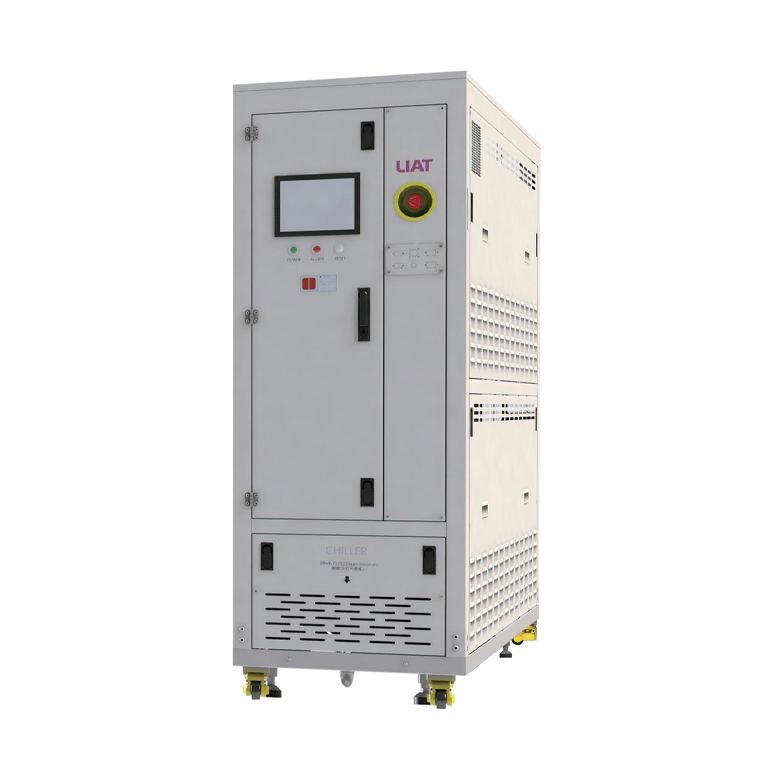
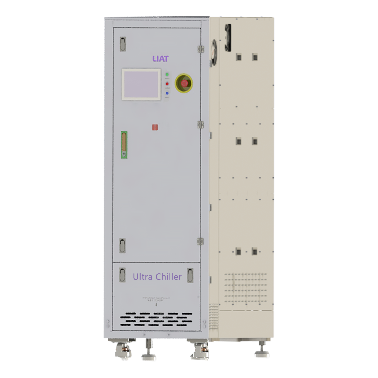
An industrial water chiller may serve a different but connected task in a semiconductor tool environment. It can remove heat from equipment enclosures, power electronics, pumps, or other liquid-cooled loads when the application calls for it. That role should be engineered separately from gas-line heating. A chiller is not a substitute for an etch gas delivery heating system, because the two systems manage different media, locations, and control objectives.
The interfaces still matter. Cooling loops can create local heat sinks near a gas manifold; cabinet airflow can remove heat; and shared utility changes can affect the surrounding environment. During design review, identify physical proximity between heated gas components and cold surfaces, specify insulation boundaries, and coordinate alarm handling so one thermal system does not obscure a developing issue in the other.
Common reasons a heated gas path becomes uneven
- Unheated discontinuities: a regulator, filter housing, or fitting sits outside the intended thermal envelope.
- Sensor location bias: the measured point is warmer than the most vulnerable point on the path.
- Insulation changes after service: a removable cover or cable route is restored differently after maintenance.
- Single-setpoint assumptions: one controller value is applied across components with very different thermal masses.
- Unreviewed utility interactions: nearby chilled surfaces or airflow alter the line’s heat-loss pattern.
A practical specification checklist
When specifying an etch gas delivery heating system, capture the operating temperature window, gas composition and source condition, pressure and flow envelope, wetted-material requirements, line length and routing, thermal zoning plan, sensor locations, insulation construction, electrical protections, control integration, alarm philosophy, and acceptance-test method. Include service access and the conditions under which the line will be opened or reconfigured. This keeps the discussion anchored to process conditions instead of a generic heater rating.
A final review should ask whether the measured thermal profile supports the intended flow behavior at the chamber-facing end of the line. If the answer relies on assumptions about an unmeasured fitting or an untested startup sequence, the design still has work to do. With a mapped path, purposeful zoning, representative testing, and coordinated utilities, an etch gas delivery heating system can help make delivery conditions more consistent from source to process tool.
 Hot News