
How to Heat Semiconductor Gas Lines Safely and Evenly
Knowing how to heat semiconductor gas lines is not simply a matter of wrapping a heater around tubing and selecting a setpoint. In a semiconductor facility, a heated gas path is part of a larger process, utility, electrical, and safety system. The target temperature, gas chemistry, line geometry, ambient exposure, pressure conditions, and tool connection all matter. From a semiconductor equipment integration perspective, the sound approach is to define those conditions first, then build a heating and verification plan around them.
The goal is a stable, documented temperature profile rather than a single warm spot near a controller. This guide explains how to heat semiconductor gas lines in a way that supports even heating while keeping the limits of a general article clear: the final design, hazardous-area assessment, electrical protection, and operating procedure should be reviewed by qualified site personnel.
Start with the process requirement, not the heater
The first step in how to heat semiconductor gas lines is to identify why the line needs heat. A line may need temperature management to keep a process condition stable, limit cold spots, support delivery consistency, or coordinate with an upstream source and downstream tool. Those are different design problems. Do not assume that a temperature used on one gas path transfers to another path.
Collect the approved process information before choosing hardware: gas identity and safety data, required temperature range, allowable temperature deviation, pressure range, tubing material and fittings, line length and diameter, insulation plan, heat-loss locations, available power, classification of the installation area, and the tool maker's connection requirements. If only a target temperature is known but the line route and ambient losses are unknown, the heating requirement is not fully defined.
For projects that also use an industrial water chiller elsewhere in the tool or utility system, keep the two control loops conceptually separate. A chiller loop may affect the surrounding thermal environment or a connected module, but it does not by itself define the correct heat-trace setpoint for a gas line. Map the thermal connections and control responsibilities before treating them as a coordinated system.
Break the line into heat zones
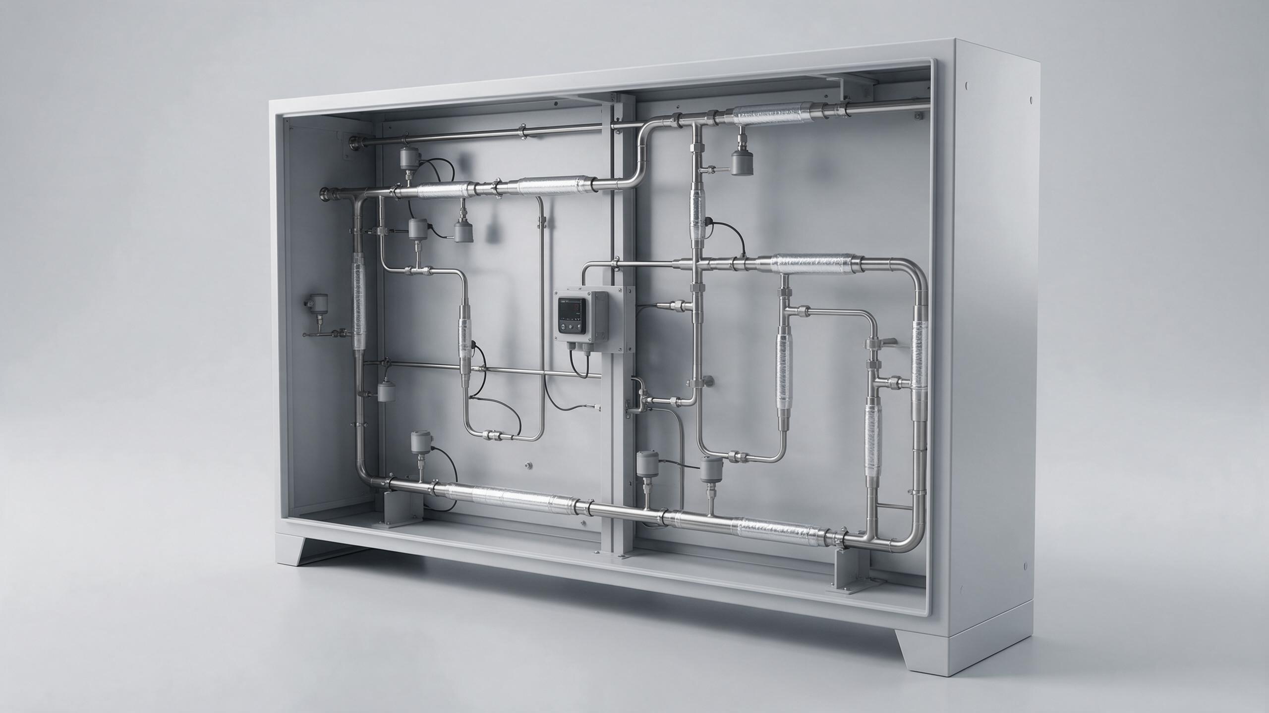
A useful answer to how to heat semiconductor gas lines is to divide the route into meaningful zones instead of applying one control decision to every meter of tubing. Straight runs, valves, regulators, filters, elbows, tool-entry sections, and sections near cold walls or exhaust paths can lose heat differently. A long run may need more than one zone when its environment or construction changes along the route.
For each zone, document the heat source, insulation coverage, sensor location, controller assignment, safety limit, power circuit, and expected heat-loss conditions. This makes it easier to see where a single sensor could mask a colder downstream section. It also creates a commissioning record that maintenance personnel can use later.
- Straight sections: check trace coverage and insulation continuity over the full length.
- Fittings and valves: review them as local thermal masses and potential heat-loss points; use the approved installation method for accessible service.
- Transitions: inspect cabinet exits, penetrations, supports, and connections with cooler assemblies because they can create temperature gradients.
- Tool connections: confirm the permitted temperature and mechanical arrangement with the equipment documentation before changing a connection zone.
Select heating, sensing, and insulation as one assembly
When planning how to heat semiconductor gas lines, the heater, sensor, controller, insulation, and mechanical installation should be treated as one assembly. Heat tracing is commonly used to stabilize a pipe or vessel surface temperature, but trace selection alone does not prove that the gas or tubing wall will be uniform at every location. Contact quality, wrapping method, overlaps, thermal bridges, insulation gaps, and sensor placement all influence the result.
Use a heat-trace product, mounting method, insulation system, enclosure, and wiring arrangement suitable for the approved location and operating conditions. Electrical safety requirements exist to address hazards such as shock, fire, and explosion; where an area classification or gas hazard is relevant, the site’s qualified electrical and process-safety teams should determine the permitted equipment and protection approach. Do not modify energized circuits or bypass a high-limit device to solve a control problem.
Place control sensors where they represent the condition that matters, not merely where installation is easiest. A sensor at a warm upstream point may produce a misleadingly comfortable reading while a valve body or downstream transition remains cooler. Where the process risk warrants it, use independently considered temperature measurement points during commissioning to compare the controller reading with the actual line profile.
Use layered control and a separate safety limit
For how to heat semiconductor gas lines, normal control and over-temperature protection serve different purposes. The controller manages the desired operating condition. An independent limit is a protective layer that should drive the system to its defined safe state when a fault, abnormal heat input, sensor issue, or control failure is detected. The specific architecture must follow the site’s approved design and applicable requirements.
Program ramping and alarms around the process procedure rather than using abrupt changes by default. Rapid heating can create a mismatch between the measured point and colder or slower-responding portions of the assembly. Define who receives alarms, what conditions require a controlled shutdown, how purge or isolation actions are coordinated, and what evidence is required before restart. The answer to how to heat semiconductor gas lines should include these operational decisions, not only a wiring diagram.
Commission for temperature uniformity
The most important field stage in how to heat semiconductor gas lines is commissioning. Inspect the installation first: confirm approved materials, trace routing, insulation closure, sensor attachment, cable condition, grounding or bonding as specified, labels, access for maintenance, and separation from incompatible components. Then verify the control sequence and high-limit response using the approved commissioning method.
Next, measure the line at enough locations to identify gradients. Include the beginning and end of each zone, fittings, low points or exposed areas, transitions, and sections adjacent to other thermal equipment. Trend results through startup, steady operation, and relevant changes in ambient or process conditions. One steady controller display is not proof of even heating.
- Confirm the approved setpoint and alarm limits against the process requirement.
- Bring zones up according to the documented startup sequence.
- Compare readings across representative locations and identify deviations.
- Correct insulation gaps, sensor placement issues, or zone-control problems under the approved change process.
- Record final settings, measurement locations, instruments, and acceptance evidence for future maintenance.
This verification mindset is especially important when an industrial water chiller changes the temperature of a nearby cabinet, platen, or utility circuit. Treat that as a condition to test, not as proof that the gas line will automatically remain uniform.
Maintain the system without losing the original design intent
Long-term how to heat semiconductor gas lines practice depends on periodic inspection and change control. Check insulation integrity, exposed sections, cable jackets, sensor attachment, controller trends, alarm history, labels, and any modifications made around the route. A recurring temperature deviation is not necessarily a heater failure; it may relate to a changed ambient condition, a shifted sensor, an altered process duty cycle, or a new connection near the line.
Before replacing a heater, controller, sensor, or insulation section, compare the change with the approved design record. If a line route, chemistry, operating range, or surrounding equipment has changed, repeat the relevant safety and commissioning review. This is more reliable than treating replacement as a like-for-like maintenance task without checking the current operating context.
A practical checklist
To summarize how to heat semiconductor gas lines, use a checklist that keeps engineering and safety decisions visible:
- Define the approved process temperature range and allowable variation.
- Map the entire line, including fittings, transitions, exposed sections, and tool connections.
- Zone the line where heat loss or construction changes.
- Select compatible heating, sensing, insulation, power, and protective devices for the reviewed conditions.
- Separate normal temperature control from independent protective limits.
- Verify uniformity at multiple locations during commissioning and retain the records.
- Reassess the system after changes to the route, process, utility environment, or surrounding thermal equipment.
In short, how to heat semiconductor gas lines safely and evenly is a controlled engineering workflow: establish the process boundary, design zones and sensors around real heat-loss conditions, verify the whole profile, and maintain the documented configuration. For a project-specific review, provide the gas-service requirements, P&ID or route drawing, target temperature range, area classification information, and relevant tool-connection documentation to the qualified engineering team.
 Hot News